background image

ISSUED: 09-19-05  SHEET #: 055-9441-5 10-31-08

Visit the Peerless Web Site at www.peerlessmounts.com

8 of 12

For customer care call 1-800-729-0307 or 708-865-8870.

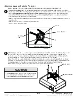
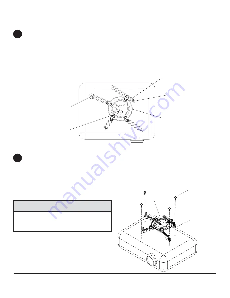
Attach adapter plate (B) to projector using one screw (G, H, I or J) for each channel as shown below. Tighten all
screws, while keeping the center of gravity. Be sure that adapter plate (B) is straight. Adjust the feet of the
channels to keep the adapter plate level. Tighten all screws with 4 mm security t-wrench (L) while keeping the
center of gravity. If M3 screws (G) are used, tighten using 2 mm security allen wrench (M).
Note: Projectors will require different size screws for mounting. Use a combination of screws (G, H, I or J) and
foot adjustment that will result in channels of adapter plate (B) fitting tightly against projector. Important: In order
to properly engage the threads in the mounting holes, the screw must be turned at least 3 full turns.
Note: If using screw (G), place washer (K) between screw (G) and foot of channel.

B

• It is the responsibility of the installer to ensure that the

projector is properly ventilated. Feet of channels are
used to raise the mount off the projector surface.

CAUTION

G, H, I or J

Generic Projector

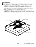
Place projector upside down. Locate adapter plate (B) with notch facing forward as close to projector center of
gravity as possible without covering any mounting holes. Loosen channels with 4 mm security t-wrench (L), and if
there are only three mounting holes remove fourth channel
. Using one channel for each mounting hole,
position feet of channels over mounting holes as shown below. Important: If projector does not have at least
three mounting holes, do not use this adapter plate.

Note: Some projectors have feet which can be removed and the corresponding threaded insert can be used for a
mounting hole.
Note: Once channels are in position retighten fasteners.

*Notch indicates front of projector.

Note: The projector you are installing may differ in appearance from the sample illustrated below.

*

Mounting
hole

B

5

6

Channel

Foot of Channel

Attaching Adapter Plate to Projector

Foot of Channel

Summary of Contents for PRS-UNV

Page 1: ...l PRS RTR Series Projector Mount Models PRS UNV PRS UNV S PRS UNV W PRS UNVP PRS UNVP S PRS UNVP W RTR UNB RTR UNS RTR UNW Maximum UL Load Capacity 25 lb 11 34 kg R This product is intended for use wi...

Page 2: ...hat the supporting surface will safely support the combined load of the equipment and all attached hard ware and components Never exceed the Maximum Load Capacity See page 1 If mounting to wood ceilin...

Page 3: ...1078 540 1078 540 1078 G M3 x 8 mm socket pin serrated washer head screw 4 510 1004 510 2004 510 2004 H M4 x 10 mm socket pin serrated washer head screw 4 510 1060 510 2060 510 2060 I M5 x 10 mm socke...

Page 4: ...uired as shown in figure 1 2 Tighten swivel stop screw against extension column flush mount tube or reducer using 4 mm security t wrench L as shown in figure 1 3 NOTE Swivel stop screw is used to jam...

Page 5: ...rench or phillips screwdriver until projector mount assembly A is firmly attached Skip to step 5 Installation To Wood Joist Ceilings C C A WOOD JOIST FRONTOF MOUNT F F WOOD JOIST A FRONTOF MOUNT 2 Ins...

Page 6: ...an damage the screws greatly reducing their holding power Never tighten in excess of 80 in lb 9 N M WARNING 3 Always attach concrete anchors directly to load bearing concrete Never attach concrete anc...

Page 7: ...r mount assembly Attach projector mount assembly A to the two 3 8 16 threaded rods using two 3 8 16 hex thin nylon insert locknuts as shown in figure 4 1 or figure 4 2 A Installation to Threaded Rod N...

Page 8: ...K between screw G and foot of channel B It is the responsibility of the installer to ensure that the projector is properly ventilated Feet of channels are used to raise the mount off the projector su...

Page 9: ...secure projector to projector mount assembly A IMPORTANT For security installations insert one 10 32 x 1 4 socket pin screw E through projector mount assembly A and into connection block as shown Tigh...

Page 10: ...Rotate mount to desired position and retighten screw To adjust pitch forward and backward tilt Using 4 mm security t wrench L security adjustment models or a phillips screwdriver non security adjustme...

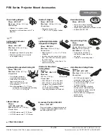
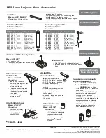
Page 11: ...tile Includes tie wire supports flush mount tube and offers two knockout panels for outlet boxes Offers unlimited adjustment for projector placement New Lightweight Suspended Ceiling Kit MODEL CMJ 45...

Page 12: ...r 2 sections Designed to externally route cords along the outside of an 1 2 extension column Sections can be stacked to create longer lengths or cut to desired length Extension Column Stabilizer Kit M...

Reviews: