61
TROUBLESHOOTING
A. ERRORS
1. When an error occurs, the pixel display on the front of
the boiler will display a wrench instead of one of the
blowers and a message will appear indicating what
the error is.
2. These error messages indicate on which burner
the error occurred: (M) for managing or (D) for
Dependent.
3. There are three kinds of errors that can occur:
a. Blocking Errors – These are errors which will
prevent the boiler from operating until the
condition which caused the error is corrected.
Then the boiler will restart without intervention.
b. Locking Errors – These errors will prevent the
boiler from operating and require a manual reset
to allow the boiler to return to operation. The
reset buttons for each burner are on the LCD
display screens located behind the right rear jacket
panel.
c. Warning Errors – These errors are typically
associated with temperature sensors (Outdoor,
DHW or Flue) with circuits that are either open or
shorted. These errors will cause the LCD screens
on the control cabinet cover to blink. These LCD
screens are located behind the right rear jacket
panel.
4. The pixel display on the front of the boiler is primarily
for status display.
B. BLOCKING ERRORS
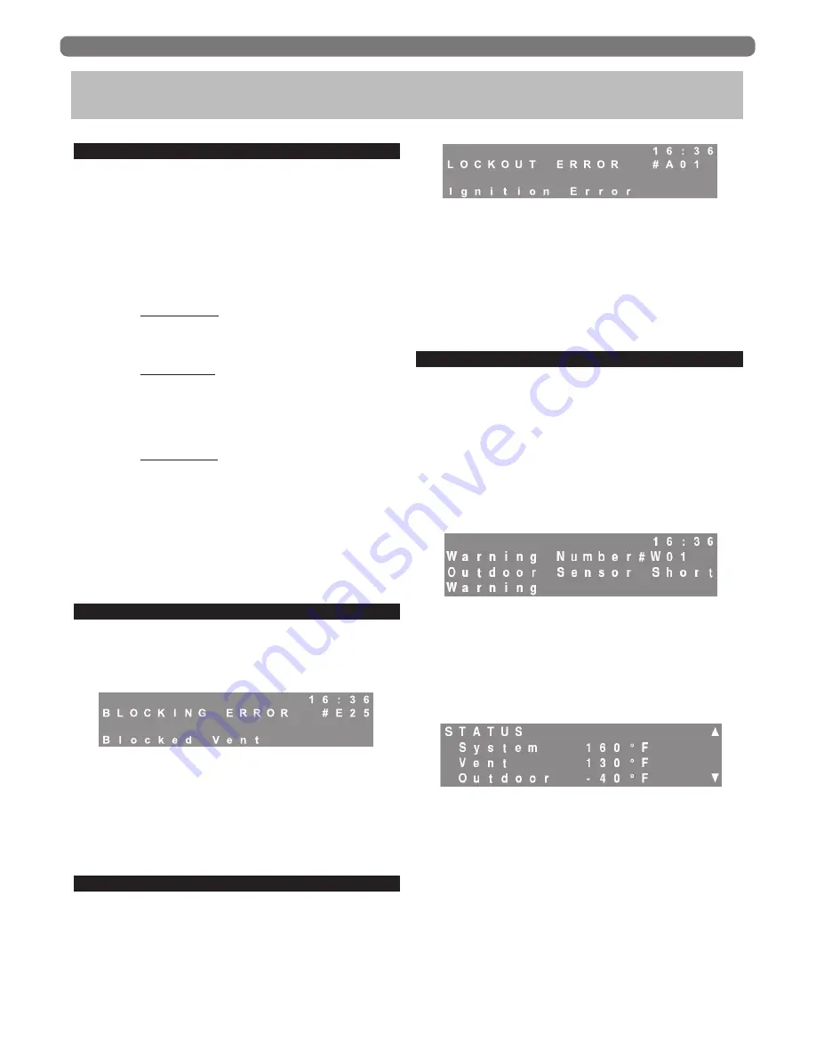
1. When a blocking error occurs, the LCD display that
corresponds to the burner with the error will show a
message in English and an “E” code (E31 Interlocks
Open).
2. Table 10.1 provides a list of blocking error codes,
descriptions and corrective actions for these errors.
3. Certain blocking errors will, if uncorrected, become
locking errors as described in the next paragraph.
C. LOCKING ERRORS
1. When a locking error occurs, the LCD display that
corresponds to the burner with the error will show a
message in English and an “A” code (A01 Ignition
Error).
2. Table 10.2 provides a list of locking error codes,
descriptions and corrective actions for these errors.
3. These errors require a manual reset of the display for
the burner with the error. These displays are located
behind the right rear jacket panel and are designated
“Managing” and “Dependent”.
D. WARNING ERRORS
The individual LCD burner displays will display a
blinking screen under several conditions. Several of these
conditions provide the error information directly on the
screen. Table 10.3 shows sensor errors and corresponding
corrective actions.
1.
Outdoor Sensor Error:
a. If the boiler control is set to a CH mode in which
an outdoor sensor is required and the sensor is
shorted, the screen will blink. Pressing the “Reset”
key will display the following error screen.
b. The boiler will not operate until this problem is
corrected.
c. If the Outdoor Sensor is open, the status screen
will read -40°F and the boiler will run at the boiler
design temperature as set up in the installer menu.
2.
DHW Sensor Error:
a. If the boiler control is set to operate on DHW
Mode 1 (DHW Sensor), and there is no sensor
connected the boiler will not satisfy a DHW call
for heat.
b. The display will blink and the DHW temperature
will read 14°F if there is an open circuit at the
sensor terminals. Pressing the “Reset” key will
display the following error screen.
10. TROUBLESHOOTING
Figure 10.1: Blocking Error Display
Figure 10.2: Locking Error Display
Figure 10.3: Warning – Outdoor Sensor Shorted
Figure 10.4: User Menu – Temperature Status Screen
Summary of Contents for PUREFIRE PFC-1000
Page 1: ...PUREFIRE Boilers PFC 850 PFC 1000 PFC 1500 Gas Installation Operation Maintenance Manual ...
Page 82: ...80 Figure 13 4 Control System REPAIR PARTS ...
Page 84: ...82 Figure 13 5 Condensate System REPAIR PARTS ...
Page 90: ...88 APPENDIX C USER MENU APPENDIX C USER MENU Figure C 1 User Menu Managing Burner ...
Page 91: ...89 APPENDIX C USER MENU Figure C 1 User Menu Dependent Burner ...
Page 92: ...90 APPENDIX D INSTALLER MENU STRUCTURE APPENDIX D INSTALLER MENU STRUCTURE ...
Page 93: ...91 APPENDIX D INSTALLER MENU STRUCTURE ...
Page 95: ...93 SERVICE LOG SERVICE LOG Date Serviced By Description of Service Serial Number ...
Page 96: ...94 NOTES ...
Page 97: ...95 NOTES ...


