Boiler Control Instruction & Operation Manual, Rev 1
Page
27
of 64
Installation
Energy Management Interface
Table 8: Modbus Signal List (continued)
Modbus
Register
Protocol
Name
Description
Read (R)/
Write (W)
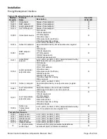
Trouble Shooting
10,034
Lockout code
Reasons for burner lockout
0
No lockout,
4
Supply high limit
5
DHW high limit
6
Stack High limit
12
Flame detected out of sequence
18
Lightoff rate proving failed
19
Purge rate proving failed
20
Invalid Safety Parameters
21
Invalid Modulation Parameter
22
Safety data verification needed
23
24VAC voltage low/high
24
Fuel Valve Error
25
Hardware Fault
26
Internal Fault
27
Ignition Failure
R
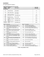
10,040
Hold code
Reason for burner hold
0
None
1
Anti short cycle
2
Boiler Safety Limit Open
3
Boiler Safety Limit Open, (ILK Off)
7
Return sensor fault
8
Supply sensor fault
9
DHW sensor fault
10
Stack sensor fault
11
Ignition failure
13
Flame rod shorted to ground
14
Delta T inlet/outlet high
15
Return temp higher than supply
16
Supply temp has risen too quickly
17
Fan speed not proved
23
24VAC voltage low/high
25
Hardware Fault
27
Ignition Failure
R
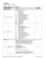
Statistics
763
Modbus command
timeout
This parameter sets the amount of time the control will
wait for input from the Building Automation System
(BAS). If the BAS does not write to the following
register within the
“Modbus Command timeout”
seconds the following inputs are considered invalid:
CH Modbus Stat,
CH Modbus Setpoint,
CH Sequencer Modbus Setpoint
CH Modbus Rate
range 30
– 120, Default 30 seconds
Other R/W registers should only be written when a
value is needed to be changed. Only the above listed
registers are stored in non-volatile registers.
R/W

