ii. Locate the opening of the exhaust vent pipe a
minimum of 12” above the air inlet opening to
prevent flue gas from recirculating to the air inlet.
b. Figure 3.7 shows vertical exhaust venting through
an unused chimney. In this case, combustion air
is supplied from inside the building. Section 1.D
provides guidelines for determining adequate
inside air.
c. Figure 3.8 illustrates another vertical venting
configuration through an unused chimney. In
this arrangement the combustion air is supplied
through the chimney as well.
D. EXHAUST VENT/AIR INTAKE PIPE SIZING
1. A list of approved venting materials for the exhaust is
provided in Table 3.1 and a list of approved materials
for air inlet is provided in Table 3.2 at the beginning
of this section.
2. The total combined length of exhaust vent and air
intake piping is 200 equivalent feet (60 m).
a. Series PFC
TM
boilers may use air from the room
in which they are installed as long as there is
adequate combustion and ventilation air provided.
See Section 1.D: Combustion and Ventilation Air
of this manual for the minimum requirements. In
this case, a maximum of 200 equivalent feet of
exhaust vent pipe can be used.
b. The equivalent length of elbows, tees and other
fittings are listed in Table 3.3.
c. The total equivalent length can be calculated as
shown in Table 3.4.
E. EXHAUST VENT/AIR INTAKE PIPE
INSTALLATION
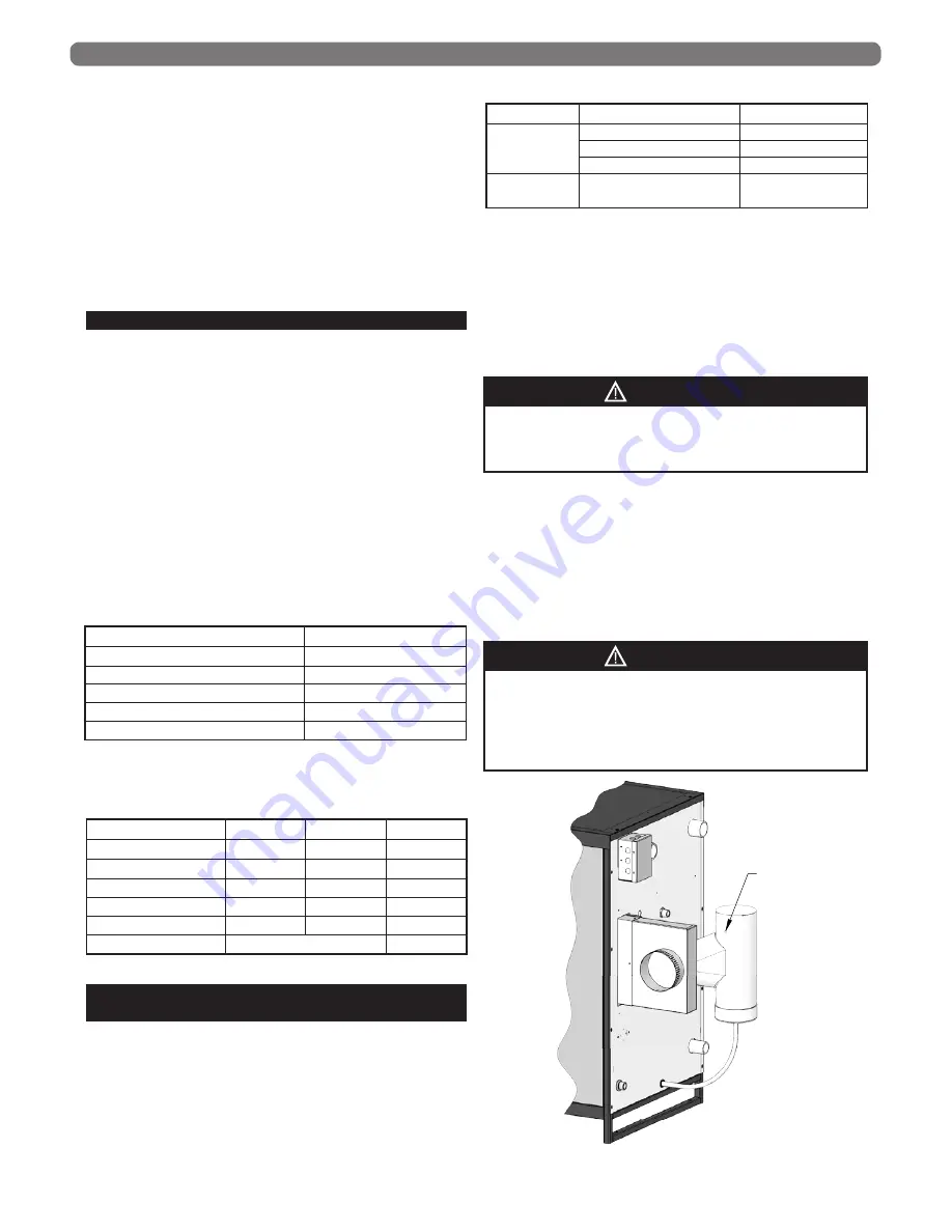
1. Figure 3.10 shows the exhaust connection on the rear
of the boiler in the middle of the rear of the boiler.
The exhaust connection is a 6” PVC/CPVC female
connection. See Table 3.5 for common adapter
fittings.
2. A condensate collection tee is required immediately
after the exhaust connection to the boiler to reduce
the vent condensate draining through the heat
exchanger. Use of an adapter from one vent material
to another is permitted between the vent connection
and tee. The tee can be a pre-fabricated component
from an approved venting material manufacturer or a
field made PVC assembly that is properly sealed and
inspected for leakage.
3. The Air Intake connection should be secured with (3)
screws and sealed.
4. Remove all burrs and debris from the joints and fittings.
5. Care should be taken to prevent dirt or debris
from entering the air intake connection. A screen is
provided inside the Air Intake fitting to prevent large
objects from entering the combustion system.
VENTING & AIR INLET PIPING
FLUE GAS
TEST PORT
Figure 3.10: Exhaust Vent Connection
This appliance uses a positive pressure venting
system. All joints must be sealed completely to
prevent leakage of flue products into living spaces.
Failure to do this may result in severe personal injury,
death or major property damage.
WARNING
Exhaust
Air Inlet
Total
Straight Length of Pipe
100’
50’
150’
90° Elbows, SR
2 x 5’= 10’
1 x 5’ = 5’
15’
45° Elbows, SR
2 x 3’ = 6’
6’
Air Intake Tee
0’
0’
Outlet Coupling
0’
0’
Total
171’
Table 3.4: Sample Equivalent Length Calculation
Table 3.3: Equivalent Length of Fittings
Fitting Description
Equivalent Length
Elbow, 90° Short Radius
5 feet (1.5 m)
Elbow, 90° Long Radius
4 feet (1.2 m)
Elbow, 45° Short Radius
3 feet (0.9 m)
Coupling
0 feet (0 m)
Air Intake Tee
0 feet (0 m)
13
Table 3.5: Exhaust Adapters PVC to Other’s
Manufacturer
Part No.
PVC to
Polypropylene
Duravent PolyPro 6”
6PPS-06PVCM-6PPF
CentroTherm InnoFlue 6”
ISAAL0606
Z-DENS 6”
2ZDCPVCG6
PVC to
Stainless Steel
Duravent
FSA-6PVCM-6FNSF
Failure to install a condensate collection tee can
shorten the lifespan of the heat exchanger and cause
blockage of the heat exchanger condensate drain.
CAUTION


