32
4. An Outdoor Sensor is provided with the Series
PFC™
boilers. It must be installed for the unit to operate
properly and to maximize the efficiency of the unit. A
warning message will be displayed on the display if
the Outdoor Sensor is not installed in the central heat
modes 1 and 2.
a. Connect the sensor to terminals #30 and #31 on
the low voltage side (right side) terminal strip.
b. The sensor should be installed in a location outside
the dwelling that is protected from harsh weather
conditions, such as driving rain and accumulated
snow, and not exposed to direct sunlight.
C. INTERNAL WIRING
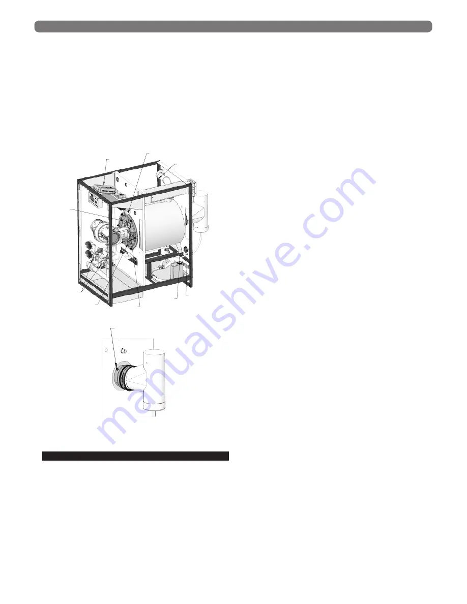
Figure 7.4 also shows all internal wiring and sensors for
Series
PFC™
boilers.
1.
User Interface:
The user interface, 975PB Display, is
attached to the front of the electrical tray behind the
smoked lens on the jacket front panel. This interface
allows users and installer to access information on the
boiler operation and change settings on the control.
(See Section 8 for more information).
2.
Primary Ignition and Safety Control:
: The ignition
control is located on the left-hand side of the electrical
tray.
3.
Relay Module:
The relay module is located in the
center back edge of the electrical tray. This fused
module provides isolation for the pump contacts on
the main control board. The maximum rating for each
pump attached is 10 Amps. Since only two pumps
operate at any one time, this limits the incoming
power required for this module to 20 Amps. This
separate power supply is to be connected to terminals
#5 and #6.
4.
Line Voltage Terminals
: The line voltage terminals
are located on the right side of the electrical tray.
Terminals #1 through #12 are the designated line
voltage terminals. They are the left-hand column of
terminals. (A more detailed description of the terminals
can be seen in Table 7.1).
5.
Low Voltage Terminals
: The low voltage terminals
are located on the right side of the electrical tray.
Terminals #13 through #35 are the designated low
voltage terminals. They are the right-hand column
of terminals. (A more detailed description of the
terminals can be seen in Table 7.2).
6.
PC Communication Adapter (Green Plug)
: The PC
Communication Adapter (PFC7008) is detached and
located inside the electrical tray, below the terminals.
This connection allows Factory Engineers to review
control settings and view advanced diagnostic
features.
7.
Return Sensor
: The return sensor is located on the
left side, above the heat exchanger. This component
monitors the return temperature inside the boiler loop.
The thermistor is a 10 k
Ω
NTC immersion sensor
with a bayonet style connection. Only use a factory
provided Series
PFC™
return sensor.
8.
Dual Supply Sensor
: The dual supply sensor is
located on the right side, above the heat exchanger,
attached to the supply line. This component contains
2 – 10 k
Ω
NTC sensors in the sensor body. The 900
control monitors the deviation between the two sensor
readings. If the deviation is too large the control will
shut down the boiler. This ensures that the supply
temperature is accurate. The dual supply sensor acts
as a high temperature limit as well.
9.
LWCO
: The low water cutoff probe is located on the
right side, above the heat exchanger, attached to the
supply line next to the dual supply sensor. This sensor
will shut down the boiler if the water level drops
below the sensor location above the heat exchanger
to ensure the boiler does not dryfire.
10.
Flue Temperature Sensor
: The flue temperature
sensor is located on the right side of the vent of
the rear of the boiler. This sensor provides flue
temperature information to the control.
11.
Blocked Vent Pressure & Blocked Condensate Drain
Float Switches
: The blocked vent pressure and
blocked condensate drain float switches are located
on the right side, beneath the heat exchanger. The
blocked vent pressure switch is a normally closed
switch that is activated when the pressure exceeds
3.5”w.c. in the vent, indicating a vent blockage. The
blocked condensate drain float switch is activated
when there is a blockage in the condensate drainage
system. When either of these switches are activated
ELECTRICAL CONNECTIONS & INTERNAL WIRING
Figure 7.2: Safety Device Locations
FLUE SENSOR
TEMPERATURE
SWITCH
RETURN SENSOR
CONDENSATE
FLOAT SWITCH
PRIMARY SAFETY
CONTROL
IGNITOR
BLOCKED VENT
SWITCH
AIR PROVING SWITCH
FLAME SENSOR
GAS VALVES
FLUE SENSOR
TEMPERATURE
SWITCH
RETURN SENSOR
CONDENSATE
FLOAT SWITCH
PRIMARY SAFETY
CONTROL
IGNITOR
BLOCKED VENT
SWITCH
AIR PROVING SWITCH
FLAME SENSOR
GAS VALVES


