background image

18 de 46

PUBLICADO: 10-30-09  HOJA #: 095-9297-2   12-04-09

Español

NOTA:

 Para instalar la placa exclusiva PLP, proceda al paso 3 de la página 20.

Quite los cuatro tornillos de 1/4-20 x .6" utilizando una llave allen de 5 mm (

I

) y afl oje los dos tornillos de 

1/4-20 x 1.25" 1/2 vuelta para poder ajustar el soporte de la pantalla.
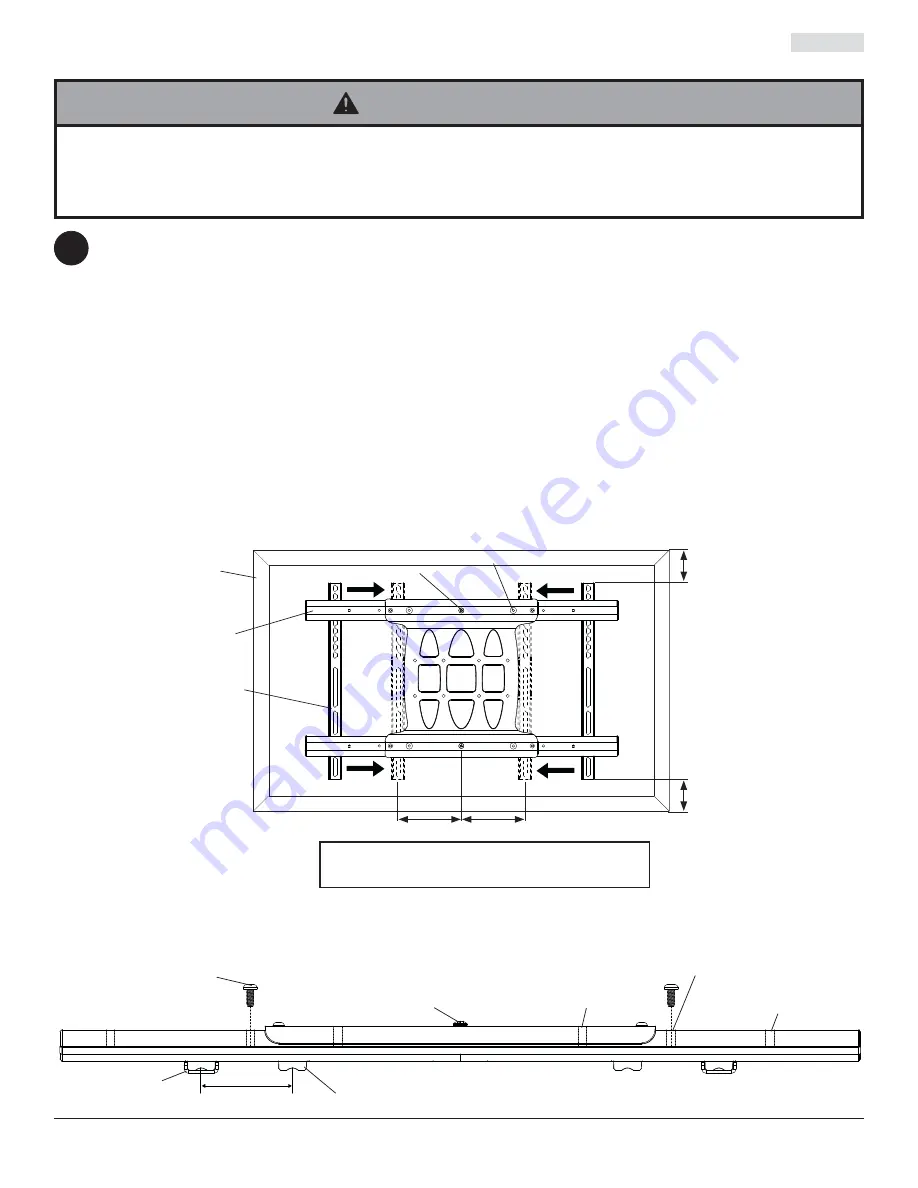
Para no rayar la pantalla, coloque un trapo sobre una superfi cie plana y nivelada que sostenga el peso de la pan-
talla. Coloque la pantalla boca abajo. Consulte las instrucciones del fabricante de la pantalla para quitar cualquier 
perilla, base, cubierta o tornillo de la parte posterior de la pantalla para prepararla para instalarle los soportes de la 
pantalla. Ajuste los soportes de la pantalla para que se alineen con los agujeros de montaje de la pantalla, como 
se muestra abajo. Escoja los tornillos pequeños, medianos, grandes o extra grandes de los sujetadores identifi ca-
dos y clasifi cados en las divisiones del empaque plástico y luego fi je los soportes de la pantalla siguiendo el paso 
2-1 o el paso 2-2 de la página 19. Vuelva a apretar los tornillos de 1/4-20 x 1.25" para limitar el movimiento de los 
soportes de la pantalla.

NOTA:

 Siempre se tienen que usar los agujeros superiores y los inferiores para la instalación de los soportes de la 

pantalla. También se deben usar los agujeros centrales en los casos en los que los sujetadores y las pantallas lo 
permitan. Verifi que que todos los agujeros estén debidamente alineados; luego, apriete los tornillos utilizando un 
destornillador phillips.

CENTRALICE LOS SOPORTES DE LA PANTALLA VERTICALMENTE 

EN LA PARTE TRASERA DE LA PANTALLA

PANTALLA

SOPORTES DE 

LA PANTALLA

SOPORTES DE 

LA PANTALLA

B

NOTA: 

Las dimensiones "X" deben ser iguales.

Las dimensiones "Y" deben ser iguales.

Y

Y

X

X

1/4-20 x 1.25" TORNILLO

1/4-20 x 1.25" 

TORNILLO

1/4-20 x .6" TORNILLO

1/4-20 x .6" TORNILLO

BLOQUE 

DESLIZABLE

2

Vuelva a instalar los cuatro tornillos de 1/4-20 x .6" utilizando una llave allen de 5 mm (

I

) en la posición fi ja de descanso 

apropiada localizada entre el soporte de la pantalla y el bloque deslizable, como se muestra en el detalle 1. Apriete los 
dos tornillos de 1/4-20 x 1.25" completamente.

DETALLE 1

VISTA SUPERIOR

POSICIÓN FIJA DE 

DESCANSO #1

POSICIÓN FIJA DE 

DESCANSO #2

POSICIÓN FIJA DE 

DESCANSO #3

Instalación de los soportes adaptadores

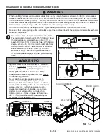
•   Apriete los tornillos de tal modo que los soportes adaptadores queden fi rmemente sujetos. No apriete aplicando demasiada 

fuerza. El apriete excesivo puede causar daño por esfuerzo a los tornillos, reduciendo enormemente su fuerza de fi jación y 
causando el posible desprendimiento de sus cabezas. Apriete los tornillos a 40 pulg-lb (4.5 N•m) de par torsor máximo. 

•   Si los tornillos no pueden atornillarse con tres vueltas completas en los insertos de la pantalla, o si los tornillos topan fondo y la 

placa todavía no está fi rmemente sujeta, se podría dañar la pantalla o causar la falla del producto.

ADVERTENCIA

Summary of Contents for SA752PU-S

Page 1: ...sal Articulating Arm Wall Mount for 32 to 52 Plasma and LCD Screens Maximum UL Load Capacity 90 lb 41 kg UL US C ISSUED 10 30 09 SHEET 095 9297 2 12 04 09 3215 W North Ave Melrose Park IL 800 865 2112...

Page 2: ...sic building construction and fully understands these instructions Make sure that the supporting surface will safely support the combined load of the equipment and all attached hardware and components...

Page 3: ...wood screws 3 520 1202 520 2165 D concrete anchors 3 590 0320 590 0320 E M10 x 5 mm socket head screw 2 520 9262 520 9534 F fastener caps 3 590 1324 590 4324 G cable ties 8 590 1168 590 1168 H 6 mm al...

Page 4: ...1031 I D 34 4 540 1059 M10 x 15 mm 4 520 9262 BLK 520 9534 SLV I D 22 4 540 1057 M6 x 30 mm 4 510 9109 M6 x 12 mm 4 520 1128 M6 x 25 mm 4 520 1208 M6 x 20 mm 4 520 9402 multi washer 6 580 1036 M4 x 2...

Page 5: ...wall plate mounting holes Installation to Single Wood Stud Wall 1 Installer must verify that the supporting surface will safely support the combined load of the equipment and all attached hardware and...

Page 6: ...25 mm minimum from the side of the block Cinder block must meet ASTM C 90 specifications It is suggested that a standard electric drill on slow setting is used to drill the hole instead of a hammer dr...

Page 7: ...and screens allow Verify that all holes are properly aligned then tighten screws using a phillips screw driver CENTER SCREEN BRACKETS VERTICALLY ON BACK OF SCREEN SCREEN SCREEN BRACKETS SCREEN BRACKET...

Page 8: ...creen Begin with longer length screw hand thread screw through multi washer screen brackets B and spacer in that order into screen as shown below Screw must make at least three full turns into the mou...

Page 9: ...en wrench H 3 1 A B B E ADAPTER PLATE ADAPTER PLATE SCREEN NOT SHOWN FOR CLARITY Do not lift more weight than you can handle Use additional man power or mechanical lifting equipment to safely handle p...

Page 10: ...Retighten tension knob ROLL Adjustment Rotate screen 5 clockwise or counter clockwise level screen then tighten M5 x 10 mm screws using 5 mm allen wrench I as shown in detail 2 FOR VERTICAL HEIGHT AD...

Page 11: ...t NOTE Make sure cables have enough slack to allow full movement of the arm Run power cable through top or bottom of arm A and signal cable s through other side of arm in order to avoid interference w...

Page 12: ...pared de brazo articulador para pantallas planas de 32 a 52 M xima capacidad de carga para UL 90 lb 41 kg UL US C PUBLICADO 10 30 09 HOJA 095 9297 2 12 04 09 3215 W North Ave Melrose Park IL 800 865 2...

Page 13: ...ontantes Se recomienda utilizar un localizador de montantes de borde a borde Siempre cuente con la ayuda de un asistente o utilice un equipo mec nico de izar para levantar y colocar el equipo con m s...

Page 14: ...520 1202 520 2165 D concreto de anclajes 3 590 0320 590 0320 E tornillos de M10 x 15 mm 2 520 9262 520 9534 F cubiertas para sujetadores 3 590 1324 590 4324 G sujetacables 8 590 1168 590 1168 H llave...

Page 15: ...25 mm 4 520 1031 I D 34 4 540 1059 M10 x 15 mm 4 520 9262 BLK 520 9534 SLV I D 22 4 540 1057 M6 x 30 mm 4 510 9109 M6 x 12 mm 4 520 1128 M6 x 25 mm 4 520 1208 M6 x 20 mm 4 520 9402 arandela m ltiple 6...

Page 16: ...sujetadores F en los agujeros de montaje de la placa de pared Instalaci n en una pared con montante de madera nico 1 7 54 192 mm C F A CP fig 1 1 fig 1 2 El instalador debe verificar que la superficie...

Page 17: ...ro percutor para evitar romper la parte trasera del agujero al entrar en un espacio o cavidad El concreto debe tener una densidad m nima de 2000 psi Un concreto menos denso podr a no ser capaz de suje...

Page 18: ...sujetadores y las pantallas lo permitan Verifique que todos los agujeros est n debidamente alineados luego apriete los tornillos utilizando un destornillador phillips CENTRALICE LOS SOPORTES DE LA PAN...

Page 19: ...uelo con la mano a trav s de la arandela m ltiple los soportes de la pantalla B y el espaciador en ese orden a la parte posterior de la pantalla como se muestra abajo El tornillo tiene que dar por lo...

Page 20: ...B B E PLACA ADAPTADORA PLACA ADAPTADORA PLACA ADAPTADORA PLACA ADAPTADORA LA PANTALLA NO SE MUESTRA PARA QUE LA IMAGEN SEA M S CLARA Instalaci n de la pantalla plana 3 1 4 TORNILLOS DE M10 X 15 MM 1...

Page 21: ...hacia delante o de 5 hacia atr s Vuelva a apretar la perilla de tensi n Ajuste de la ROTACI N Rote la pantalla 5 en el sentido de las manecillas del reloj o en el sentido contrario nivele la pantalla...

Page 22: ...os cables de la se al por el otro lado del brazo para evitar que haya interferencia con la se al Asegure los cordones en su lugar colocando las cubiertas de los cables J y K a presi n sobre el soporte...

Page 23: ...uraux pour crans plats articul s pour crans de 32 52 pouces Capacit de charge UL maximale 90 lb 41 kg UL US C PUBLI LE 10 30 09 FEUILLE no 095 9297 2 12 04 09 3215 W North Ave Melrose Park IL 800 865...

Page 24: ...mur montants en bois assurez vous que les vis de montage sont ancr es au centre des montants L utilisation d un localisateur de montants bord bord est fortement recommand e Pour lever et positionner...

Page 25: ...bois 3 520 1202 520 2165 D concreto d ancrage 3 590 0320 590 0320 E vis M10 x 15 mm 2 520 9262 520 9534 F embouts de fixation 3 590 1324 590 4324 G attaches de c ble 8 590 1168 590 1168 H hexagonale d...

Page 26: ...mm 4 520 1031 I D 34 4 540 1059 M10 x 15 mm 4 520 9262 BLK 520 9534 SLV I D 22 4 540 1057 M6 x 30 mm 4 510 9109 M6 x 12 mm 4 520 1128 M6 x 25 mm 4 520 1208 M6 x 20 mm 4 520 9402 rondelle univer selle...

Page 27: ...s rez trois embouts de fixation F dans les trous de fixation de la plaque murale 1 7 54 192 mm C F A CE fig 1 1 fig 1 2 Installation sur un mur montant en bois L installateur doit s assurer que la sur...

Page 28: ...d un marteau perforateur afin d viter de briser la partie arri re du trou lorsque vous p n trez un vide ou une cavit Le b ton doit avoir une densit minimum de 2 000 psi Un b ton de densit moindre risq...

Page 29: ...es trous de fixation sup rieurs et inf rieurs pour fixer les supports de l cran Les trous du milieu devraient galement tre utilis s lorsque les fixations et l cran le permettent Veillez ce que tous le...

Page 30: ...le type d cran Commencez par la vis la plus longue et vissez la manuellement l cran en la faisant passer travers la rondelle tout usage les supports de l cran B et l entretoise comme indiqu ci dessou...

Page 31: ...3 et 3 4 3 1 A B B E CRAN NON ILLUSTR POUR PLUS DE CLART Ne soulevez pas plus que votre capacit Faites vous aider par une autre personne ou utilisez un syst me de levage m canique pour effectuer une i...

Page 32: ...re r gl e un maximum de 10 vers l avant ou 5 vers l arri re Resserrez le bouton de serrage R glage du PIVOTEMENT LAT RAL Faites pivoter l cran de 5 dans le sens horaire ou antihoraire mettez l cran de...

Page 33: ...s d interconnexion dans l autre c t du bras afin d viter de brouiller le signal Faites tenir les c bles en place en pressant les cache c bles J et K sur le support Il se peut que vous deviez d placer...

Page 34: ...Gelenkarm Wandhalter f r Flachbildschirme von 32 52 Zoll Maximale UL Tragf higkeit 90 lb 41 kg UL US C AUSGEGEBEN 10 30 09 BLATT NR 095 9297 2 12 04 09 3215 W North Ave Melrose Park IL 800 865 2112 or...

Page 35: ...nleitungen vollkommen verstehen Vergewissern Sie sich dass die tragende Fl che das Gesamtgewicht der Ger te und allen daran angebrachten Befestigungsteilen und Komponenten sicher tragen kann Die maxim...

Page 36: ...auben 3 520 1202 520 2165 D Beton D bel 3 590 0320 590 0320 E M10 x 15 mm Schrauben 2 520 9262 520 9534 F Befestigungsteilabdeckungen 3 590 1324 590 4324 G Kabelbinder 8 590 1168 590 1168 H 6 mm Inbus...

Page 37: ...x 25 mm 4 520 1031 I D 34 4 540 1059 M10 x 15 mm 4 520 9262 BLK 520 9534 SLV I D 22 4 540 1057 M6 x 30 mm 4 510 9109 M6 x 12 mm 4 520 1128 M6 x 25 mm 4 520 1208 M6 x 20 mm 4 520 9402 Mehrloch scheibe...

Page 38: ...gungsteilabdeckungen F in die Montagebohrungen der Wandplatte ein 1 7 54 192 mm C F A WANDPLATTE CS Anbringung an W nden mit einer Holzst nderreihe Bei der Anbringung muss darauf geachtet werden dass...

Page 39: ...Bohrungsr ckseite beim Eintritt in einen Leer oder Hohlraum ausbricht Die Betondruckfestigkeit muss mindestens 2000 psi betragen In Beton mit geringerer Druckfestigkeit kann der Betond bel u U nicht h...

Page 40: ...ngen sind die oberen und unteren Montagebohrungen zu verwen den Wo immer mit den jeweiligen Befestigungsteilen und Bildschirmen m glich sollten auch die mittleren Bohrun gen verwendet werden Achten Si...

Page 41: ...ie nachstehend dargestellt von Hand durch die Mehrlochscheibe die Bildschirmhalterungen B und den Abstandhalter in dieser Reihenfolge in den Bildschirm Die Schraube muss sich um mindestens drei volle...

Page 42: ...schl ssel H an 3 1 A B B E ADAPTERPLATTE ADAPTERPLATTE BILDSCHIRM ZUR BESSEREN VERANSCHAULICHUNG NICHT DARGESTELLT Anbringung des Flachbildschirms 3 1 4 1 4 M10 X 15 MM SCHRAUBEN M10 X 15 MM SCHRAUBEN...

Page 43: ...hinten Ziehen Sie den Spannknopf wieder an QUERNEIGUNGSEINSTELLUNG Drehen Sie den Bildschirm um 5 nach rechts oder links richten Sie ihn waagerecht aus und ziehen Sie dann die M5 x 10 mm Schrauben mit...

Page 44: ...n Arm A und das die Signalkabel auf der anderen Seite um Signalst rungen zu verhindern Sichern Sie die Kabel indem Sie die Kabelabdeckungen J und K auf den Halter dr cken Der Bildschirm muss eventuell...

Page 45: ...NTY Espa ol www peerlessmounts com 2008 Peerless Industries Inc Peerless Industries Inc establece un per odo de garant a de cinco a os para los productos fabricados o suministrados por Peerless Este p...

Page 46: ...en oder gelieferten Produkt aufzuerlegen Diese Garantie verleiht Ihnen bestimmte gesetzliche Rechte und Sie verf gen u U ber weitere Rechte unter der nationalen Gesetzgebung des Landes in dem dieses P...

Reviews: