background image

4 of 8

ISSUED: 10-31-05  SHEET #: 202-9011-2 01-29-07

Installation to Wood Stud Wall

• Tighten wood screws so that wall plate is firmly

attached, but do not overtighten. Overtightening can
damage the screws, greatly reducing their holding
power.

• Never tighten in excess of 80 in. • lb (9 N.M.).

• Make sure that mounting screws are anchored into

the center of the stud. The use of an "edge to edge"
stud finder is highly recommended.

WARNING

• Make sure that the supporting surface will safely support the combined load of the equipment and all attached

hardware and components.

WARNING

CC

AA

CS = center of screen
CL = stud centerline

fig 1.3

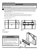
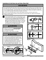
Using a stud finder, locate the edges of the wood studs used in mounting this product. Use of an edge-to-edge stud
finder is highly recommended. Based on its edges and using a level, draw a vertical line down the center of each
stud. Mark a point (point 1) on the right stud centerline 4-5/8" above the center of screen as shown in figure 1.1.
Hold wall plate (AA) over point 1. Using a level to ensure plate is horizontal, mark three more points (points 2,3,
and 4
) as shown in figure 1.2.

Drill 5/32" diameter holes 2-1/2" deep through studs at the four points.

Loosely fasten wall plate (AA) to wall using four #14 x 2-1/2" wood screws (CC) as shown in figure 1.3.

Note: For ease of installation, start with the top right wood screw first and work counterclockwise.

Level, hold, and then tighten all screws.

Skip to step 2 on page 6.

fig 1.1

1

4-5/8"

(117 mm)

CL

POINT 1

POINT 1

POINT 2

POINT 3

POINT 4

CL

CL

CL

fig 1.2

CS

CS

Summary of Contents for SF 24D

Page 1: ...acity 200 lb 90 7 kg 3215 W North Ave Melrose Park IL 60160 800 729 0307 or 708 865 8870 Fax 708 865 2941 www peerlessmounts com ISSUED 10 31 05 SHEET 202 9011 2 01 29 07 Features Ultra slim design ho...

Page 2: ...d level 6 mm allen wrench Do not begin to install your Peerless product until you have read and understood the instructions and warnings contained in this Installation Sheet If you have any questions...

Page 3: ...D EE Description Qty Part AA wall plate 1 200 1796 BB interface plate 1 200 0860 CC 14 x 2 5 wood screw 4 5S1 015 C03 DD Alligator anchor 4 590 0097 EE M10 x 1 5 x 15 mm socket head screw 4 520 9262 F...

Page 4: ...the wood studs used in mounting this product Use of an edge to edge stud finder is highly recommended Based on its edges and using a level draw a vertical line down the center of each stud Mark a poi...

Page 5: ...ll mounts on cinder block verify that you have a minimum of 1 3 8 of actual concrete thickness in the hole to be used for the concrete anchors Do not drill into mortar joints Be sure to mount in a sol...

Page 6: ...mm socket head screws EE as shown in figures 2 1 portrait or 2 2 landscape 2 Installing Interface Bracket Tighten screws so adapter brackets are firmly attached Do not tighten with excessive force Ove...

Page 7: ...plate as shown in figures 2 3 portrait or 2 4 landscape 2 Installing Interface Bracket to LC Adapter Plate Tighten screws so adapter brackets are firmly attached Do not tighten with excessive force O...

Page 8: ...to wall plate AA Then slowly swing screen in as shown Turn security screw using security allen wrench FF clockwise at least six times to prevent screen from being removed as shown in detail 1 Screen c...

Reviews: