11 of 22
ISSUED: 4-03-07 SHEET #: 202-9177-5 02-15-10
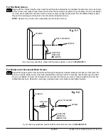
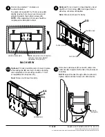
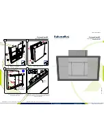
Roll can be adjusted 1° clockwise or
counterclockwise.
To adjust roll, loosen M10 x 15 mm screws (
K
)
slightly, leaving them snug. Level screen and
adapter brackets, then tighten screws (
K
) .
NOTE:
When adjusting roll, screws should be
retightened as indicated in step 4.
Slide one mesh sleeve (
F
) over each cable. Use
cable ties (
G
) to tighten both ends of mesh sleeves
to cables.
NOTE:
loop cable ties through cable mounts and
tighten cable and mesh sleeve to cable mounts.
F
BACK VIEW
CABLE
MOUNTS
© 2008, Peerless Industries, Inc. All rights reserved.
All other brand and product names are trademarks or registered trademarks of their respective owners.
8
10
9
11
G
SCREEN FASTENER
NOTE:
MOUNTING PLATE SHOWN
WITHOUT FULL WALL MOUNT
ASSEMBLY FOR CLARITY.
Optional:
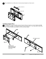
To lock mount in closed position, insert
one M5 x 40 mm screw (
DD
) into tapped hole in
either top or bottom of flat plate.
Note:
Screen not shown for clarity.
FLAT PLATE
TAPPED HOLE
DD
TAPPED HOLE
Optional:
To lock one sliding arm of mount in place,
slide locking tab (
B
) over top or bottom of sliding
arm and attach to mount using one M5 x 10 mm
screw (
AA
) and one spacer (
C
).
Note:
Screen not shown for clarity.
SLIDING ARM
B
C
AA


