background image

8 of 22

ISSUED: 4-03-07  SHEET #: 202-9177-5   02-15-10

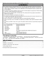
Note:

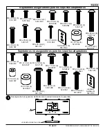
 "X" dimensions should be equal.

•  Tighten screws so adapter brackets are firmly attached. Do not tighten with excessive force. Overtightening can 

cause stress damage to screws, greatly reducing their holding power and possibly causing screw heads to become 
detached.


Tighten to 40 in. • lb (4.5 N.M.) maximum torque.

•  If screws don't get three complete turns in the screen inserts or if screws bottom out and bracket is still not tightly 

secured, damage may occur to screen or product may fail.

WARNING

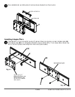
Installing Adapter Brackets

To prevent scratching the screen, set a cloth on a flat, level surface that will support the weight of the screen. Place 
screen face side down. Refer to screen manufacturers instructions or customer service, for removing any knobs, 
base, cover, or screw(s) on the back of the screen to prepare mounting. These need to be removed to allow the 
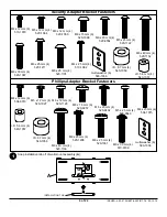
adapter brackets to be attached. Select the small, medium, large or extra large screws from the baffled fastener 
pack then attach adapter brackets (

FF

 or 

GG

) to screen following figure 5.1 or 5.2.

NOTE:

 Top and bottom mounting holes on screen must be used for attaching brackets. Verify that all holes are 

properly aligned, and then tighten screws using a phillips screwdriver.

FF 

or 

GG

CENTER 

BRACKETS 

VERTICALLY 

ON BACK OF 

SCREEN

X

X

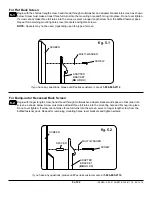
NOTE: 

For 

flat back screens

 proceed to step 5-1. For 

bump-out or recessed back screen

 skip to step 5-2.

MEDIUM HOLE FOR M5 SCREWS

SMALL HOLE FOR M4 SCREWS

LARGE HOLE FOR M6 SCREWS

Notes:


•  The number of fasteners used will vary, depending upon 

the type of screen.

•  Multi-washers and spacers may not be used, depending 

upon the type of screen.

•  Use the corresponding hole in the multi- washer that 

matches your screw size as shown.

MULTI-WASHER

5

Summary of Contents for SmartMount SP850-UNL

Page 1: ...with Universal Adapter Bracket for 32 58 Flat Panel Screens Models SP850 UNL SP850 UNLP SP850 UNL S SP850 UNLP S 3215 W North Ave Melrose Park IL 60160 800 865 2112 or 708 865 8870 Fax 708 865 2941 www peerlessmounts com Maximum Load Capacity 150 lb 68 kg ...

Page 2: ...stalled by someone of good mechanical aptitude has experience with basic building construction and fully understands these instructions Make sure that the supporting surface will safely support the combined load of the equipment and all attached hardware and components Never exceed the Maximum Load Capacity See page one If mounting to wood wall studs make sure that mounting screws are anchored int...

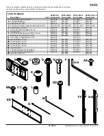
Page 3: ...sleeve 2 600 1014 600 1014 600 1014 600 1014 G cable tie 4 560 9711 560 9711 560 9711 560 9711 K M10 x 15 mm socket head screw 4 520 9262 520 9262 520 9262 520 9262 L 198 x 313 x 437H retaining spacer 4 590 5005 590 5005 590 5005 590 5005 M 4 mm security allen wrench 1 560 1146 n a 560 1146 n a AA M5 x 10 mm socket pin screw 5 520 1063 520 1233 520 1063 520 1233 BB M4 x 12 mm socket pin screw 4 51...

Page 4: ...4 M6 x 30 mm 4 520 1067 M8 x 15 mm 6 520 1068 M8 x 40 mm 4 520 1152 M8 x 25 mm 4 520 1101 M6 x 20 mm 4 520 9402 M6 x 30 mm 4 510 9109 multi washer 6 580 1036 M8 x 16 mm 6 520 9257 M8 x 40 mm 4 520 1136 M4 x 12 mm 6 504 9013 Phillips Adapter Bracket Fasteners M4 x 25 mm 4 504 1015 M5 x 12 mm 4 520 1027 M5 x 25 mm 4 520 9543 M6 x 12 mm 4 520 1128 M6 x 25 mm 4 520 1208 I D 5 6 mm 4 540 1057 M8 x 25 m...

Page 5: ...ots on the right and left stud centerlines Drill 5 32 diameter holes 2 1 2 deep through studs at the two points Using two 14 x 2 1 2 wood screws fasten bottom of wall mount assembly to wall as shown in figure 2 3 Skip to step 3 on page 7 fig 2 1 2 CL POINT 1 CL POINT 2 fig 2 3 D Installer must verify that the supporting surface will safely support the combined load of the equipment and all attached h...

Page 6: ...g out the back of the hole when entering a void or cavity Concrete must be 2000 psi density minimum Lighter density concrete may not hold concrete anchor Make sure that the supporting surface will safely support the combined load of the equipment and all attached hard ware and components WARNING D A fig 2 5 SOLID CONCRETE CINDER BLOCK E CUTAWAY VIEW INCORRECT concrete plaster drywall A CORRECT conc...

Page 7: ...to mounting plate and attach using two bottom M10 x 15 mm screws K as shown in fig ures 4 1 and 4 2 Tighten screws using 6 mm allen wrench not included K fig 4 1 MOUNTING PLATE NOTE MOUNTING PLATE SHOWN WITHOUT FULL WALL MOUNT ASSEMBLY FOR CLARITY EE K MOUNTING PLATE fig 4 2 EE INSTALLATION TAB A SLIDING ARM Place installation tab over sliding arms of wall mount assembly A to lock them in place 3 4 ...

Page 8: ...oving any knobs base cover or screw s on the back of the screen to prepare mounting These need to be removed to allow the adapter brackets to be attached Select the small medium large or extra large screws from the baffled fastener pack then attach adapter brackets FF or GG to screen following figure 5 1 or 5 2 NOTE Top and bottom mounting holes on screen must be used for attaching brackets Verify t...

Page 9: ... screw hand thread through multi washer adapter bracket and spacer in that order into screen as shown below Screw must make at least three full turns into the mounting hole and fit snug into place Do not over tighten If screw cannot make three full turns into the screen select a longer length screw from the baffled fastener pack Repeat for remaining mounting holes level brackets and tighten screws F...

Page 10: ... lifting equipment to safely lift and position the plasma television WARNING Screen can tilt 5 or 10 forward NOTE Screen must be securely attached to mounting plate with all fasteners before adjusting tilt To tilt screen 5 forward lift and pull mounting plate forward until middle notch rests on M6 screw as shown in figure 7 1 Tighten M6 screw both sides and M10 screws both sides To tilt screen 10 f...

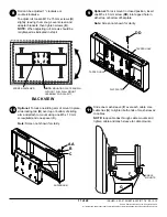
Page 11: ...ts F BACK VIEW CABLE MOUNTS 2008 Peerless Industries Inc All rights reserved All other brand and product names are trademarks or registered trademarks of their respective owners 8 10 9 11 G SCREEN FASTENER NOTE MOUNTING PLATE SHOWN WITHOUT FULL WALL MOUNT ASSEMBLY FOR CLARITY Optional To lock mount in closed position insert one M5 x 40 mm screw DD into tapped hole in either top or bottom of flat pl...

Page 12: ...de pared con soporte adaptador para pantallas planas de 32 a 58 Modelos SP850 UNL SP850 UNLP SP850 UNL S SP850 UNLP S 3215 W North Ave Melrose Park IL 60160 800 865 2112 or 708 865 8870 Fax 708 865 2941 www peerlessmounts com Capacidad de carga máxima 150 lb 68 kg ...

Page 13: ...na aptitud mecánica que tenga experien cia en construcción básica de edificios y que entienda estas instrucciones en su totalidad Asegúrese de que la superficie de apoyo sostendrá con seguridad la carga combinada del equipo y todos los fi jadores y componentes Nunca sobrepase la capacidad máxima de soportar carga Vea la página 12 Si va a instalar el producto en una pared con montantes de madera asegú...

Page 14: ...0 0097 590 0097 590 0097 590 0097 F Funda de malla de poliéster de 18 2 600 1014 600 1014 600 1014 600 1014 G Sujetacables 4 560 9711 560 9711 560 9711 560 9711 K tornillo de cabeza hueca de M10 x 15 mm 4 520 9262 520 9262 520 9262 520 9262 L Espaciador de retención de 437 4 590 5005 590 5005 590 5005 590 5005 M Llave allen de seguridad de 4 mm 1 560 1146 560 1146 AA tornillo de M5 x 10 mm 5 520 1...

Page 15: ... 520 1067 M8 x 15 mm 6 520 1068 M8 x 40 mm 4 520 1152 M8 x 25 mm 4 520 1101 M6 x 20 mm 4 520 9402 M6 x 30 mm 4 510 9109 arandela múltiple 6 580 1036 M8 x 16 mm 6 520 9257 M8 x 40 mm 4 520 1136 M4 x 12 mm 6 504 9013 Sujetadores no aseguradores para los soportes adaptadores M4 x 25 mm 4 504 1015 M5 x 12 mm 4 520 1027 M5 x 25 mm 4 520 9543 M6 x 12 mm 4 520 1128 M6 x 25 mm 4 520 1208 I D 5 6 mm 4 540 ...

Page 16: ...ás para las ranuras inferiores en las líneas que trazó por el centro del montante derecho y del izquierdo Taladre agujeros de 5 32 de diámetro y 2 1 2 de profundidad a través de los soportes en los dos puntos Utilizando dos tornillos para madera de 14 x 2 1 2 fije la parte inferior de la unidad del soporte de pared a la pared como se muestra en la figura 2 3 Pase al paso 3 de la página 18 fig 2 1 2 L...

Page 17: ... para concreto no se separen del concreto cuando apriete los tornillos Si el grosor de la capa de yeso o tabique de yeso cartón tiene un grosor mayor de 5 8 el instalador tiene que suministrar las fijaciones especiales no aprobado por UL ADVERTENCIA Instalación en una pared de concreto macizo o de bloques de hormigón de escorias Cuando vaya a instalar soportes de pared de Peerless en bloques de hor...

Page 18: ...tilizan do los dos tornillos inferiores de M10 x 15 mm K como se muestra en las figuras 4 1 y 4 2 Apriete los tornillos usando una llave allen de 6 mm no incluida K fig 4 1 PLACA DE MONTAJE NOTA LA PLACA DE MONTAJE SE MUESTRA SIN LA UNIDAD DEL SOPO RTE DE PARED COMPLETA PARA QUE LA IMAGEN SEA MÁS CLARA EE K PLACA DE MONTAJE fig 4 2 EE 4 LENGÜETA DE INSTALACIÓN A BRAZO DESLIZABLE Coloque la lengüeta d...

Page 19: ...nstalación Hay que quitar dichos artículos para que los soportes adaptadores se puedan fijar Escoja los tornillos pequeños medianos grandes o extra grandes de los sujetadores identificados y clasificados en las divisiones del empaque plástico y luego fije los soportes adaptadores FF o GG a la pantalla siguiendo la figura 5 1 o la figura 5 2 NOTA Siempre se tienen que usar los agujeros superiores y los i...

Page 20: ...avés de la arandela el soporte adaptador y el espaciador en ese orden a la parte posterior de la pantalla como se muestra abajo El tornillo debe dar por lo menos tres vueltas completas dentro del agujero de instalación y debe quedar ajustado en su lugar No apriete los tornillos en exceso Si el tornillo no puede dar tres vueltas completas al entrar en la parte posterior de la pantalla seleccione un...

Page 21: ...lana con más seguridad ADVERTENCIA La pantalla se puede inclinar 5 o 10 hacia adelante NOTA La pantalla tiene que estar fijada con seguridad a la placa de montaje con todos los sujetadores antes de ajustar la inclinación Para inclinar la pantalla 5 hacia adelante levante la placa de montaje y tire de ella hacia adelante hasta que la muesca del medio quede sobre el tornillo de M6 como se muestra en ...

Page 22: ... no se muestra para que la imagen sea más clara PLACA PLANA AGUJERO ROSCADO DD AGUJERO ROSCADO Opcional Para trabar uno de los brazos de la unidad del soporte en su lugar deslice la lengüeta trabadora B por encima o por debajo del brazo deslizable y fíjela a la unidad utilizando un tornillo de M5 x 10 mm AA y un espaciador C NOTA La pantalla no se muestra para que la imagen sea más clara BRAZO DES...

Reviews: