background image

4 of 6

ISSUED: 07-03-02   SHEET #: 200-9386-6  01-25-11

Visit the Peerless Web Site at www.peerlessindustries.com

For customer service call 1-800-729-0307 or 708-865-8870.

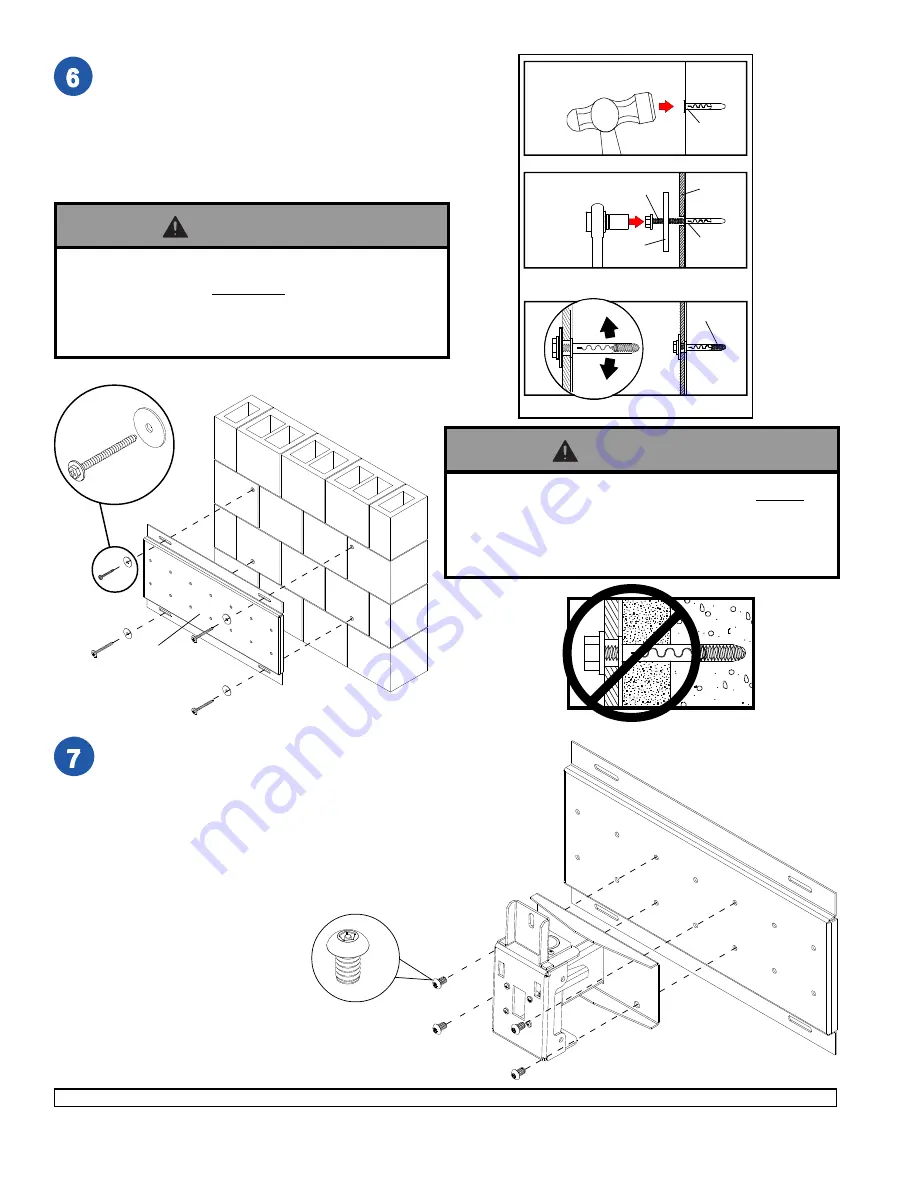
For Concrete Walls

 drill four 1/4" (6 mm) dia. holes to a

minimum depth of 2.5" (64 mm) on marks made in step
1. Insert anchor (

M

) in holes flush with wall as shown

(right). Place wall plate (

L

) over anchor and secure with

four #14 x 2.5" (6 mm x 65 mm) wood screws and
washers (

N

) as shown at bottom of page. Make sure

wall plate is level before placing fasteners. Tighten all
fasteners.

CUT

A

W

A

Y

 VIEW

1

3

2

Drill holes and insert anchors (

M

) in four places

Level wall plate and tighten four screws (

O

).

Place wall plate (

L

) over anchors (

M

) and fasten

with screws (

O

) and washers (

N

). Do not tighten.

concrete

N

O

L

M

M

NOTE: Five mounting positions, center position shown
to the right.

Attach wall arm assembly (

J

) to wall plate (

L

) using four

M10 penta-pin screws (

F

).

L

J

F

O

L

O

N

• Always attach concrete expansion anchors directly to

load-bearing concrete.

• Never attach concrete expansion anchors to concrete

covered with plaster, drywall, or other finishing material.

WARNING

• Tighten wood screws so that wall plate is firmly

attached, but do not overtighten. Overtightening can
damage screws, greatly reducing their holding power.

• Never tighten in excess of 80 in • lb (9 N.M.).

WARNING

Summary of Contents for Solid-Point PS 1

Page 1: ... 32 x 1 2 socket pin screws C as shown Before you start make sure all parts listed are included with your product PART QTY DESCRIPTION A 200 1434 1 rotation box B 200 1877 1 tilt pivot retainer assembly C 520 1055 2 10 32 x 1 2 socket pin screw D 200 0288 1 pitch roll assembly E 520 1001 1 carriage bolt 3 8 16 x 3 F 520 9263 12 M10 x 1 5 x 15 mm penta pin screw G 590 1087 1 tilt adjustment knob H ...

Page 2: ...and style D GENERIC ADAPTER BRACKET TILT BRACKET CENTER BOLT GENERIC ADAPTER BRACKET RETAINING SPACER WASHER SLOT M5 SCREW BRACKET CARRIAGE BOLT DETAIL 4 DO NOT REMOVE M5 SCREWS For vertical orientation unscrew two M5 screws until screw is able to move freely in slot of tilt bracket as shown in details 4 and 4A Hold adapter bracket stationary and rotate tilt bracket 90 by hand or using a lever exa...

Page 3: ...encil L Tighten wood screws so that wall plate is firmly attached but do not overtighten Overtightening can damage screws greatly reducing their holding power Never tighten in excess of 80 in lb 9 N M Make sure that mounting screws are anchored into the center of the studs The use of an edge to edge stud finder is highly recommended WARNING When installing Peerless wall mounts on cinder block veri...

Page 4: ... 3 2 Drill holes and insert anchors M in four places Level wall plate and tighten four screws O Place wall plate L over anchors M and fasten with screws O and washers N Do not tighten concrete N O L M M NOTE Fivemountingpositions centerpositionshown to the right Attach wall arm assembly J to wall plate L using four M10 penta pin screws F L J F O L O N Always attach concrete expansion anchors direc...

Page 5: ...stall tilt adjustment knob G Install remaining two M10 penta pin screws F HAND TIGHTEN all four M10 penta pin screws F to allow for tilt adjustment Remove tape from carriage bolt E For tilt adjustment gently push back on the top of plasma to relieve pressure on knob Adjust tilt to desired position and tighten tilt adjustment knob G then securely tighten all four M10 screws F using penta pin driver...

Page 6: ...icult to adjust roll of plasma torque may be adjusted by following the procedures below Adjust tilt adjustment knob G to allow maximum tilt Insert 3 4 open end wrench not provided into side of pitch roll assembly D and rotate center bolt counter clockwise to loosen torque IMPORTANT Do not loosen or tighten more than 1 8 turn CENTER BOLT PLASMA A D ADAPTER PLATE PLASMA D CENTER BOLT WRENCH G NOTE R...

Reviews: