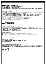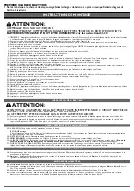
CAUTION:
ADULT ASSEMBLY REQUIRED.
USE CARE WHEN UNPACKING AS COMPONENTS TO BE ASSEMBLED MAY POSE A SMALL PARTS/SHARP EDGE
HAZARD.
BATTERY IS INCLUDED AND MUST BE CONNECTED; see instructions 31-32
1 • IMPORTANT: Apply decals to simulated coil springs before installing them. Push the 2 rear simulated coil springs into the slots, ensuring that the sides are
correct (right and left are indicated on the back of the items, DX = right side)
2 • Push the side trim section into the 2 slots in the chassis. Fit the other trim section on the opposite side.
3 • Install the roll-bar support, first engaging the rear section and then the front. Fit the other side in the same way.
4 • Secure the supports with the screws provided.
5 • Place the top of the rollbar. Mantain the holes represented by the letter A on the front and the holes represented by the letter B to the rear of the vehicle.
6 • Secure the roll bar using pressure to engage the 2 self-threading screws, one on each side.
7 • Attach the three plastic rings to rollbar. The holes position is up and down the back of the vehicle.
8 • Mount the three fog lights on the roof bars and attach them with the screws provided (one per light).
9 • Apply the silver mylar decals in the 2 rear light areas.
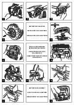
10 • Push the rear lights into the respective slots.
11 • Position the seat as required (the seat can be fitted in 2 positions) and secure it with the 2 screws provided. Secure the other seat in the same way.
12 • Insert the 2 seatbelt buckles into the respective central slots between the seats, as shown in the figure.
13 • Install the 2 ring clamps on the roll bar, one on each side, opening them to position them correctly.
14 • Fix the 2 belts to the respective ring clamps with the screws provided.
15 • Apply the speedometer decal and push to install the transparent cover. Now install the speedometer to the dashboard, inserting first the tongue and then the
tooth.
16 • Install the dashboard cover, inserting first the upper teeth and then the lower, as shown in the figure.
17 • Join the two sections of the steering wheel.
18 •Insert the horn into the central hole of the steering wheel, following the instructions included in its packaging.
19 • Remove the plastic protector from the steering shaft. Install the steering wheel on the steering column, lining up the respective holes.
20 • On one side insert the screw and on one other the nut, and fix the steering wheel as shown in the figure.
21 • Install the two parts of the windshield as shown. Picture A shows the grille fitted correctly
22 • Secure the grille with the three screws.
23 • Place the windshield on the hood hooking the three central tabs.
24 • Fit the windscreen of the vehicle with screws.
25 • IMPORTANT: Apply decals to simulated coil springs before installing them. Snap fit the 2 remaining simulated coil springs, ensuring that the sides are correct
(right and left are indicated on the back of the items, DX = right side).
26 • Fit the front grill engaging it to the chassis at the 6 points highlighted in detail A.
27 • Screw on the grill with the 2 screws provided.
28 • Apply the silver mylar decals in the 2 front light areas.
29 • Push the front lights into the respective slots.
30 • Install the 4 small hubcaps.
BATTERY INSTALLATION
WARNING:
WARNING: BATTERY CHARGING AND ANY OTHER OPERATION ON THE ELECTRICAL SYSTEM MUST BE
CARRIED OUT BY ADULTS ONLY.
THE BATTERY CAN ALSO BE CHARGED WITHOUT REMOVING IT FROM THE VEHICLE.
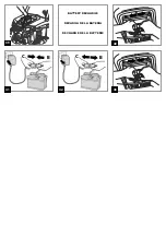
31 • Open the battery compartment by rotating the red catch to the lock open position. Connect the electrical system plug with the battery plug.
32 • Close the battery compartment by inserting the cover at the front below the cover plate. Complete the operation by inserting the red catch and rotating it
180º using a coin. The vehicle is now ready for use.
VEHICLE FEATURES AND INSTRUCTIONS FOR USE
33 • A: HORN. Press the yellow button to sound the horn.
B: Passenger HANDHOLD.
C: Electrical accelerator and brake pedal. When accelerator is pressed completely down, forward motion is activated. Brake activates automatically when the
child takes his foot off the accelerator.
34 • Rear DRINK HOLDERS. There are dual drink holders in the rear box.
35 • ADJUSTABLE SEATS. The seats can be adjusted in 2 positions as the child grows, as shown in the figure.
36 • GEAR SHIFT LEVER: when received the vehicle speed is limited to first gear (
1
- see figure). It also has a reverse (
R - for safety, shifter must be held in
reverse to back up
), and a second gear (
2
) recommended only for expert drivers.
37 • TO ACCESS HIGH SPEED To enable the second gear, unscrew the red stop on the gear lever. Rotate the stop 90°, as shown in the figure, and secure in
position with the screw. Now by pulling back the gear lever the vehicle can run in second gear.
BATTERY REPLACEMENT
38 • Use a coin to open the battery compartment. Disconnect the battery from the system. Remove the 2 screws from the battery holder in the compartment.
39 • Replace the expired battery. Re-install the battery holder back in place and secure it with the screws. Connect the two plugs, close the battery compartment
and fasten it shut.
BATTERY RECHARGE
40 • Disconnect plug
A
of the electrical system from plug
B
of the battery by pressing laterally.
41 • Connect the battery charger to a domestic power outlet according to the instructions included with the charger. Connect plug
B
with plug
C
of the battery
charger.
42 • When charging is complete, disconnect the battery charger from the power outlet and then disconnect plug
C
from plug
B
.
43 • Fully insert plug
B
into plug
A
, until it snaps into position. At the end of charging operations always remember to insert and fix the battery holder. Close the
battery compartment and secure it with the catch.
ASSEMBLY INSTRUCTIONS
INITIAL BATTERY CHARGE
!
• Remove battery and charger from packaging. Connect battery charger to a 120vac wall recepticle. Connect battery charger to battery.
Summary of Contents for IGOD0074
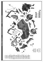
Page 3: ...20 25 13 17 16 15 19 7 8 9 10 A 18 Apply decals before installing 12 14 A 21 22 23 24 26 A...
Page 5: ...43 B A B A 39 40 B C 41 BATTERY RECHARGE RECARGA DE LA BATER A RECHARGE DE LA BATTERIE B C 42...
Page 6: ...b blue bk black r red w white b azul bk negro r rojo w blanco b bleu bk noir r rouge w blanc...
Page 23: ......


