CAUTION:
ADULT ASSEMBLY REQUIRED.
USE CARE WHEN UNPACKING AS
COMPONENTS TO BE ASSEMBLED
MAY POSE A SMALL PARTS/SHARP
EDGE HAZARD.
IF THE PRODUCT IS DAMAGED
WHEN YOU OPEN THE
PACKAGING, CONTACT THE
SERVICE CENTER AND DO NOT
USE THE PRODUCT.
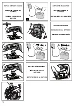
BATTERY IS INCLUDED
AND MUST BE INSTALLED;
see instructions 29-30
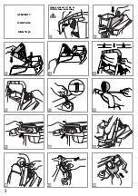
1 •IMPORTANT: Apply decals to simulated
coil springs before installing them. Push the
2 rear simulated coil springs into the slots,
ensuring that the sides are correct (right
and left are indicated on the back of the
items, DX = right side)
2 •Push the side trim section into the 2 slots
in the chassis. Fit the other trim section on
the opposite side.
3 •Install the roll-bar support, first engaging
the rear section and then the front. Fit the
other side in the same way.
4 •Secure the supports with the screws
provided.
5 •Place the top of the rollbar. Mantain the
holes represented by the letter A on the
front and the holes represented by the
letter B to the rear of the vehicle.
6 •Fix the roll bar using pressure to engage
the 2 self-threading screws, one on each
side.
7 •Attach the three plastic rings to rollbar.
The holes position is up and down the
back of the vehicle.
8 •Mount the three fog lights on the roof bars
and attach them with the screws provided
(one per light).
9 •Apply the silver mylar decals in the 2 rear
light areas.
10 •Push the rear lights into the respective
slots.
11 •Position the seat as required (the seat can
be fitted in 2 positions) and secure it with
the 2 screws provided. Secure the other
seat in the same way.
12 •Install the 2 ring clamps on the roll bar,
one on each side, opening them to
position them correctly.
ASSEMBLY INSTRUCTIONS
ATTENTION:
ASSEMBLAGE PAR UN ADULTE
REQUIS.
OUVRIR LES EMBALLAGES AVEC
PRÉCAUTION CAR LES PIÈCES À
ASSEMBLER PEUVENT
COMPORTER DES RISQUES DE
COUPURES OU DE BLESSURES.
SI LE PRODUIT EST ENDOMMAGÉ
LORSQUE VOUS OUVREZ
L’EMBALLAGE, CONTACTEZ LE
SERVICE APRÈS-VENTE ET
N’UTILISEZ PAS LE PRODUIT.
LA BATTERIE EST INCLUSE
ET DOIT ETRE
CONNECTÉE; voir les
instructions 29-30
1 •IMPORTANT : Appliquez les adhésifs sur
les ressorts hélicoïdaux simulés avant de
les installer. Poussez les 2 ressorts
hélicoïdaux simulés arrière dans les fentes
en veillant à ce que les côtés soient
corrects (la droite et la gauche sont
indiquées à l'arrière des articles, DX =
côté droit).
2 •Poussez la section du bord latéral dans les
2 fentes du châssis. Réglez l'autre section
de bord de l'autre côté.
3 •Installez le support de l'arceau de sécurité
en enclenchant en premier la section
arrière, puis la section avant. Réglez l'autre
côté de la même façon.
4 •Fixez les supports à l'aide des vis fournies.
5 •Sur la traverse de l’arceau de sécurité, vous
verrez 3 zones évidées pour les bagues
légères ; NOTE : l’évidement le plus large
(dessin B) doit être tourné vers l’arrière.
Placer la traverse sur les tubes verticaux.
6 •Continuer en serrant à fond les 2 vis
autotaraudeuses, de part et d’autre de
l’arceau de sécurité.
7 •Monter les 3 bagues légères de l’arceau de
sécurité avec les trous pour les vis vers
l’arrière et vers le haut.
8 •Fixer les phares antibrouillard sur le toit
avec les vis fournies (une par phare)
9 •Appliquez les adhésifs en mylar argenté
dans les 2 zones de feux arrière.
10 •Poussez les feux arrière dans les fentes
respectives.
11 •Positionnez le siège tel que requis (le siège
peut être réglé en 2 positions) et fixez-le à
l'aide des 2 vis fournies. Fixez l'autre siège
de la même façon.
12 •Installez les 2 bagues de serrage sur
l'arceau de sécurité, de chaque côté, en les
ouvrant pour les mettre à la bonne
position.
INSTRUCTIONS D'ASSEMBLAGE
PRECAUTION:
REQUIERE MONTAJE DE UN
ADULTO. ALGUNOS
COMPONENTES AL SER
ENSAMBLADOS PODRÍAN TENER
PARTES PEQUEÑAS/RIESGO POR
BORDES CONTANTES.
SI AL ABRIR EL PAQUETE SE
NOTASEN DAÑOS EN EL
PRODUCTO, CONTACTE CON EL
CENTRO DE ASISTENCIA. NO
UTILICE EL PRODUCTO.
LA BATERÍA VIENE
INCLUIDA, SOLO NECESITA
INSTALARSE. Vea
instrucciónes 29-30
1 •IMPORTANTE: Aplicar las pegatinas a los
amortiguadores cilíndricos simulados antes
de instalarlos. Insertar los 2
amortiguadores cilíndricos simulados
posteriores en los huecos
correspondientes, teniendo en cuenta los
lados correctos (la indicación se encuentra
en la parte trasera de las piezas: DX = lado
derecho)
2 •Insertar a presión la protección lateral en
los 2 huecos del chasis. A continuación,
insertar la protección del lado opuesto.
3 •Colocar el soporte de la barra, insertando
primero la parte posterior y, a
continuación, la parte anterior. Colocar el
otro soporte de la misma manera.
4 •Atornillar ambos soportes con los tornillos
que se suministran.
5 •En la barra transversal soporte, se
observan 3 hendiduras para los soportes
de las luces; NOTA: la hendidura más ancha
(ilus. B) debe estar orientada hacia la parte
posterior. Insertar la barra transversal en
los tubos verticales.
6 •Continuar atornillando con fuerza la barra
mediante los 2 tornillos autorroscantes,
uno por cada lado.
7 •Montar 3 abrazaderas de soporte para las
luces sobre la barra soporte orientando
los orificios para los tornillos hacia la parte
posterior y superior.
8 •Aplicar los tres faros antiniebla en el techo,
atornillando los tornillos puestos a
disposición (uno para cada faro).
9 •Aplicar los adhesivos plateados en los
receptáculos de los 2 faros posteriores.
10 •Colocar a presión los faros posteriores en
los huecos correspondientes.
11 •Colocar el asiento en la posición deseada
(puede colocarse en 2 posiciones
diferentes) y fijarlo con los dos tornillos
que se suministran. A continuación, colocar
y fijar el otro asiento del mismo modo.
12 •Colocar las 2 anillas sobre la barra, unir en
cada lado, abriéndolas para colocarlas en
su sitio.
INSTRUCCIONES DE MONTAJE
ENGLISH
FRANÇAIS
ESPAÑOL
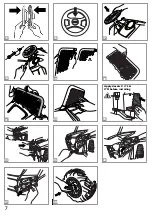
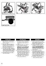
13 •Apply the speedometer decal and push to
install the transparent cover. Now install
the speedometer to the dashboard,
inserting first the tongue and then the
tooth.
13 •Appliquez l'adhésif de l'indicateur de
vitesse et poussez pour installer la
couverture transparente. Installez à
présent l'indicateur de vitesse sur le
tableau de bord en insérant d'abord la
languette, puis la dent.
13 •Aplicar el adhesivo del velocímetro en
insertar la cubierta transparente a presión.
A continuación, colocar el velocímetro en
el salpicadero, insertando primero la
lengüeta y luego el diente.
14 •Montar la cubierta del salpicadero,
14 •Install the dashboard cover, inserting
first the upper teeth and then the
lower, as shown in the figure.
14 •Installez le cache du tableau de bord en
insérant en premier la dent supérieure,
puis l'inférieure, comme indiqué dans
l'image.
insertando primero los dientes superiores
y luego los inferiores, como se muestra en
la figura.
6


