50
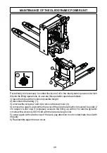
TILLER ALIGNMENT ADJUSTING
Periodically it is necessary to check that the direction of the truck is aligned with the
direction set up from the tiller; if it is necessary execute the alignment again between
tiller and traction wheel, it need:
1) disconnect the battery (1);
2) unscrew the screws (2 and 4) to remove the rear cover (3);
3) loosen the screw (5) of the chain sprocket on the traction wheel stearing column until
this in free to rotate;
4) align the tiller with the traction wheel checking the direction of the truck for short
stretch.
5) tighten with force the screw of the chain sprocket keyed on the traction wheel stearing
column. If the screw tends to loosen again, replace the grower washer.
6) Reassemble the rear cover
5
3
1
4
2
1
51
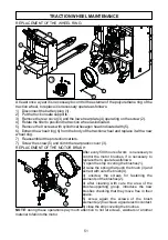
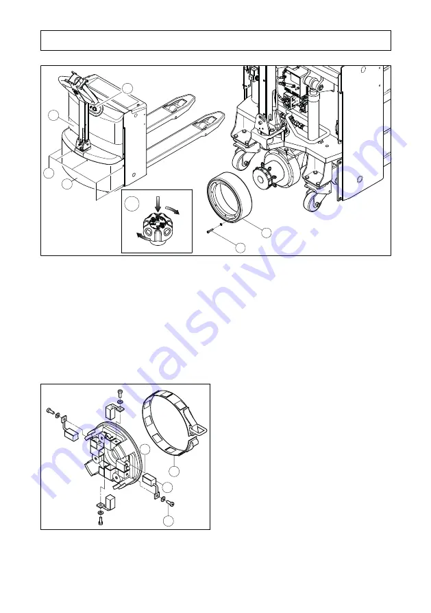
TRACTION WHEEL MAINTENANCE
REPLACEMENT OF THE WHEEL RING:
At least once a year it is necessary to control the external of the polyurethane ring of the
traction wheel, to replace it is necessary operate as follows:
1) Disconnect the battery plug (1).
2) Put the truck on safe supports..
3) Remove the rear cover (3) and the lower rear plate (4) operating on the screw (2).
4) Rotate the tiller to position the traction wheel as indicated.
5) Remove the 8 screws with cylindrical hexagon head indicated with (5).
6) Extract the wheel ring (6) from the body of the traction wheel and replace it with a new
wheel ring.
7) Reassembled the protection carters.
7) Screw the screw (5) and climb the rear plastic cover (3).
5
6
2
4
3
1
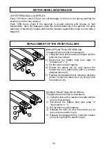
REPLACEMENT OF THE MOTOR BRUSH
After every 500 hours of work is necessary to
control the motor brushes, if is necessary to
replace them, operate as follows:
1) open the strip covering the brushes (1).
2) raise the spring that push the brush (3) and
extract with care the brush (4).
3) unscrew the screws for fastening the
elements of the brushes (2).
4) after cleaning with care the area of the
brush-supporting group, introduce the new
brushes checking that they move free in their
space.
5) screw again the screws of the brush
elements (2) to achieve a good electric contact.
6) close the strip covering the brushes.
NOTE
: during these operations pay much attention to not let screws, washers or another
material to fall into the motor.
3
1
4
2
1
Summary of Contents for TPL 16-20-30
Page 1: ...MANUALE D USO E MANUTENZIONE TPL 16 20 30 IT UK ...
Page 26: ...26 NOTE ...
Page 27: ...27 MAINTENANCE USER MANUAL TPL 16 20 30 UK ...
Page 33: ...33 DIMENSIONS SCHEME AND TECHNICAL SPECIFICATIONS PAPER ROLL VERSION ...
Page 54: ...54 NOTE ...
Page 55: ...55 NOTE ...
Page 57: ...GUÍA PARA EL USO Y EL MANTENIMIENTO TPL 16 20 30 ES PT ...
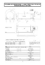
Page 63: ...7 ESQUEMA DE DIMENSIONES Y CARACTERÍSTICAS TÉCNICAS VERSIÓN RODILLO DE PAPEL ...
Page 84: ...28 NOTAS ...
Page 85: ...29 MANUAL DE USO E MANUTENÇÃO TPL 16 20 30 PT ...
Page 91: ...35 ESQUEMA DE DIMENSÕES E ESPECIFICAÇÕES TÉCNICAS VERSÃO ROLO DE PAPEL ...

