Rev. 02-21 Page 33
USER MANUAL
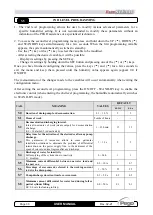
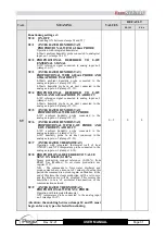
VAR.
MEANING
VALUES
DEFAULT
ES-3M
ES-6
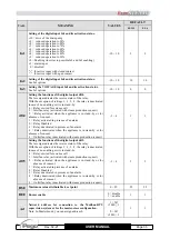
In1
Setting of the digital input In1 and its activation status.
±10 = drive of the drain pump
±9 = reduced operation to 90%
±8 = reduced operation to 80%
±7 = reduced operation to 70%
±6 = reduced operation to 60%
±5 = reduced operation to 50%
±4 = reduced operation to 40%
±3 = reduced operation to 30%
±2 = Enabling (in series to possible In2 and In3 enabling)
±1 = alarm input
0 = disabled
“+” for active input with closed contact
“-“ for active input with open contact
-10 ÷ 10
2
2
In2
Setting of the digital input In2 and its activation status.
See In1 options
-10 ÷ 10
10
10
In3
Setting the VOLTAGE input In3 and its activation status.
See In1 options
-10 ÷ 10
0
0
dO4
Setting the functions of the digital output dO4.
The less sign indicates the reverse status of the relay.
With the exception of settings 1, -1, 2, -2, the relay is deactivated
in case of no enabling or it is in stand-by.
4 = Relay excited for essence call
3 = Inlet fan relay (activated with steam production request)
2 = Relay activated when the appliance is in stand-by or for
absence of consent.
1 = Relay activated in presence of an alarm
0 = Relay Disabled
-1 = Relay deactivated in presence of an alarm
-2 = Relay deactivated when the appliance is in stand-by or for
absence of consent.
-3 = Outlet fan relay (deactivated with steam production request)
-3 ÷ 4
1
1
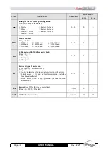
dO5
Setting the functions of the digital output dO5.
The less sign indicates the reverse status of the relay.
With the exception of settings 1, -1, 2, -2, the relay is deactivated
in case of no enabling or it is in stand-by.
4 = Relay excited for essence call
3 = Inlet fan relay (activated with steam production request)
2 = Relay activated when the appliance is in stand-by or for
absence of consent.
1 = Relay activated in presence of an alarm
0 = Relay Disabled
-1 = Relay deactivated in presence of an alarm
-2 = Relay deactivated when the appliance is in stand-by or for
absence of consent.
-3 = Outlet fan relay (deactivated with steam production request)
-3 ÷ 4
3
3
HSE
Maximum value attributable to set point
0 ÷ 99
99
99
BEE
Buzzer enable
0 = disable
1 = enable
1
1
Ad
Network address for connection to the Modbus-RTU
supervision system or for the master-slave configuration.
Note: In Master mode, you can assign address 0.
1 ÷ 247
if MS ≤ 1
0 ÷ 247
if MS > 1
1
1

