background image


Rev. 02-21                                                                                                   Page 37


USER MANUAL 

Description of operation: 

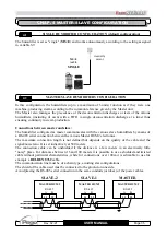
The unit configured as Master constantly communicates with the connected slaves through the RS-
485  connection,  indicating  the  quantity  of  steam  to  be  produced  (0-100%)  and  managing  the 
priorities of the various units in relation to discharges for deconcentration or testing.  
The operating mode of the Master/Slave unit is only set on the Master by means of the variable S9, 
as  well as  the possible connection of the ambient  humidity probe, the humidity probe in the duct, 
the 0-10V reference signal, the ON-OFF enablement and the humidity setting.  
The variable Pr, which represents the percentage of steam production at full capacity, is instead set 
on each individual unit. 
 
The absence of consent (clamps 24 and 25 open on Master HUM2 board) behaves as follows: 

On the Master unit, it stops the same Master unit and all the connected slave units (flashing 
OFF). 

On the Slave units, stop only the slave unit concerned (OFF flashing). 

 
Stand-by by means of the dedicated key behaves as follows: 

If  activated  on  the  Master  unit,  it  puts  the  machine  in  stand-by  mode  (LED  flashes  on  the 

stand-by key) and brings the steam production request of the connected slaves to zero. 

On the Slave units, it stops only the concerned slave unit by putting the machine in stand-by 

mode (LED flashes on the stand-by key). 

 
If  the  Master  cannot  communicate  with  a  slave,  after  a  15-second  timeout  time  it  signals  the 
problem with an alarm that can be silenced (E7). The interrogation of the slave continues and if the 
communication resumes, the error is reset automatically. 
If  a  Slave  is  not  queried  by  the  Master  within  a  timeout  period  of  15  seconds,  it  considers 
interrupted  the  connection  and  therefore  leads  to  0  the  production  of  steam,  disconnecting  the 
electrodes and signalling the anomaly with an alarm that can be silenced (E7). If the connection is 
resumed, the alarm is reset automatically and normal operation is resumed. 
 
On the humidifiers configured as Slaves (MS = 1), the variable S9 is not  considered; for them the 
production  of  steam  follows  in  a  proportional  way  the  data  sent  by  the  Master  on  the  RS485 
connection. 


Management of priorities of discharges for deconcentration and tests: 

The priorities for deconcentration discharges and for diagnostic tests are managed as follows: 
The  Slave  units,  when  interrogated,  send  the  eventual  water  discharge  request  to  the  Master  that 
manages them with a FIFO (first input / first output). 
The Master waits 3 minutes before giving the next consent to the waiting unit, following the priority 
in the FIFO; this allows the unit that is discharging the water to resume steam production.  
The Slave unit that requested a discharge waits for the consent from the Master for 45 minutes, after 
which it is executed anyway (Time out). 


Summary of Contents for EASYSTEAM 400ES3MOEMCCU

Page 1: ...Rel 19 Use and maintenance manual READ AND KEEP REV 02 21 ENG IMMERSED ELECTRODES HUMIDIFIERS EASYSTEAM ES OEM CCU...

Page 2: ...anual Instructions for disposal The humidifier is made up of metal parts and plastic parts In reference to European Union directive 2012 19 EC issued on 4 July 2012 and the related national legislatio...

Page 3: ...odbus RTU protocol Page 20 2 7 Board power supply Page 20 2 8 NANO EasySTEAM Display for Master HUM2 board Page 21 2 9 ES OEM CCU series electrical layouts Page 23 2 10 Installing the ES OEM CCU serie...

Page 4: ...cylinder Page 47 7 5 Cleaning the cylinder STEAM DISTRIBUTION Page 48 8 1 Generality Page 48 8 2 Example of distribution in air duct Page 49 8 3 Example of distribution in ambient Page 49 8 4 Choosing...

Page 5: ...utomatic functioning In fact it is possible to set the maximum capacity of steam production values of production capacity intermediate in percentage the frequency of deconcentration discharges the dis...

Page 6: ...ranty can be refused when the equipment is modified or transformed Under no circumstances Pego S r l will be liable for any loss of data and information costs of goods or substitute services damage to...

Page 7: ...trolling the load solenoid valve to raise the water level in the cylinder or the drain pump to lower it it succeeds to control this phenomenon in an absolutely automatic way Furthermore thanks to a mi...

Page 8: ...ioning due to very low conductivity or high hardness or because it s too aggressive the below is a summary table of the parameters required for correct humidifier functioning POTABLE WATER FUNCTIONING...

Page 9: ...50Hz POWER kW 2 4 5 ABSORBED CURRENT A 9 6 5 TYPE OF CONTROL Display NANO Master HUM2 EASYSTEAM ES MINI series ELECTRONIC CONTROL POWER SUPPLY 230V 50 60Hz STEAM OUTLET DIAMETER mm 25 25 CYLINDERS NU...

Page 10: ...r water load Nr 1 32mm external diameter connection for water discharge Nr 1 25mm external diameter connection for the steam tube Nr 1 User manual Nr 1 Test checklist which reports Humidifier model De...

Page 11: ...th these values 6 Do not install and use the humidifier near products or objects that can be damaged in contact with water or the humidity produced 7 Avoid placing power cables with signal cables in t...

Page 12: ...apter 2 4 15 With the default setting of parameter In1 2 the humidifier to work requires the digital input 1 to be enabled by means of a voltage free contact terminals 24 and 25 on the electronic boar...

Page 13: ...after sales assistance to verify the hardware compatibility between the probe and the humidifier S9 0 ON OFF Functioning This type of operation involves the production of steam in only 2 modes no prod...

Page 14: ...this value Example if the proportional band is set on default value 10 5 set point value and humidity is set at 50 below 45 the humidifier will work at 100 of steam production above 55 the humidifier...

Page 15: ...nformation on the humidity probe in air duct refer to chapter 3 Programming variables StC r0 t1 S9 4 PROPORTIONAL functioning with 0 10Vdc reference signal humidity probe in air duct 4 20mA This type...

Page 16: ...ier will work at 100 of steam production above 55 the humidifier will not produce steam Between 45 and 55 the humidifier will optimally regulate steam production S9 6 PROPORTIONAL functioning with 0 1...

Page 17: ...or another three seconds the state is switched Inlet fan dO4 or dO5 3 The inlet fan is usually used to introduce or mix the steam in the room The relay linked to this function is activated when there...

Page 18: ...ent MODBUS RTU_UMIDMS03 S9 9 PROPORTIONAL functioning with NTC ambient temperature probe INTEGRATED THERMOSTAT This type of operation involves proportional steam production the humidifier will automat...

Page 19: ...d on the second level variable In3 The input is active with phase input to clamp 6 Input In4 clamps 4 neutral and 5 phase input for maximum water level in the cylinder active with phase input to clamp...

Page 20: ...ion of 5VA only electronic part Power supply clamps 2 and 3 230Vac 50 60Hz power supply NANO EASYSTEAM DISPLAY FOR MASTER HUM2 ELECTRONIC BOARD The Master HUM2 electronics is the heart of the humidifi...

Page 21: ...ut model 400ES3MOEMCCU 40 40 2 9 Fan unit Closed emergency contact Level Humidifier electrodes Connector Power terminal box Consents and probes terminal box LEGEND KM1 Contactor TA1 Amperometric trans...

Page 22: ...CCU 40 40 Fan unit Closed emergency contact Level Humidifier electrodes Connector Power terminal board LEGEND KM1 Contactor TA1 Amperometric transf P1 Discharge pump EV1 Charge valve Power supply 400V...

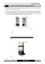
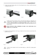
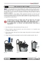
Page 23: ...of the appliance 2 By removing the O ring that holds it to the back remove the cylinder from the lower flange extracting it upwards and remove it from the humidifier Fix the humidifier to the wall pos...

Page 24: ...to the drain sleeve and have vertical development for at least the first 50cm Make sure that you do not create bottlenecks and do not exceed with its height at any point in the path the level of the...

Page 25: ...rmful substances DO NOT MAKE BOTTLENECKS SIPHONS OR LENGTHS GREATER THAN 5 METERS To correctly connect the steam distribution line carefully read chapter 8 STEAM DISTRIBUTION OEM SERIES POWER SUPPLY E...

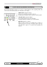
Page 26: ...amming Decrease values Scroll down the parameters During the main display Activates the manual water discharge STAND BY SILENCE Pressed for more than 2 seconds alternates the Stand by status to the no...

Page 27: ...s the percentage relative humidity SET visible and adjustable by pressing the SET key COMBINATION OF KEYS 1ST LEVEL PROGRAMMING If pressed simultaneously for more than 3 seconds they allow access to t...

Page 28: ...ower Solid power supply Ok and consent is present Flashing power supply Ok but no consent or stand by present YELLOW LED initialled S Status Solid Steam production powered electrodes Flashing Discharg...

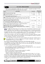
Page 29: ...not produce steam Between 45 and 55 the humidifier will optimally regulate steam production The Pr steam percentage is the value the humidifier can reach at maximum production leaving setting at 100...

Page 30: ...el programming press the ON OFF STAND BY key to enable the electronic control when entering the 2nd level programming the humidifier automatically switches to STAND BY mode VAR MEANING VALUES DEFAULT...

Page 31: ...nalogue input no 2 clamps 16 17 S9 6 INTEGRATED HUMIDISTAT PROPORTIONAL WITH 0 10V PROBE AND 0 10V PROBE IN AIR DUCT 0 10V ambient humidity probe connected to the analogue input no 2 clamps 16 17 0 10...

Page 32: ...essence if the above conditions are satisfied used only when S9 7 or 9 0 99 min 5 min 5 min t4 Timer for manual insertion of outlet fans Function that can be activated manually with the key combinati...

Page 33: ...ance is in stand by or for absence of consent 1 Relay activated in presence of an alarm 0 Relay Disabled 1 Relay deactivated in presence of an alarm 2 Relay deactivated when the appliance is in stand...

Page 34: ...ud 5 9600 baud 8 38400 baud 0 8 5 5 Prt Configuration of the Modbus parity check Range 0 2 0 No parity 1 Even parity 2 Odd parity 0 2 0 0 P1 Password type of protection active when PA is different fro...

Page 35: ...a RS 485 serial connection between the various Master HUM2 electronics The maximum connection length is not defined but depends on the quality of the cable and the signal noise ratio It is set indica...

Page 36: ...Master Slave1 Slave2 Slave3 Slave4 6 with Control Master Slave1 Slave2 Slave3 Slave4 Slave5 Parameters configuration in Slave1 unit Ad 1 Ad Master 1 MS 1 slave Parameters configuration in Slave2 unit...

Page 37: ...n stand by mode LED flashes on the stand by key If the Master cannot communicate with a slave after a 15 second timeout time it signals the problem with an alarm that can be silenced E7 The interrogat...

Page 38: ...or give ON OFF or 0 10V consent in the ON OFF or PROPORTIONAL 0 10V models 2 Allow the cylinder to fill up until the water starts boiling then completely empty the cylinder with the MANUAL DRAIN key t...

Page 39: ...code Maximum water level in the cylinder The water inside the cylinder has reached the maximum level sensor and the absorbed current is within a permitted range 0 5A during this alarm there is no aco...

Page 40: ...sent in the water loading line may cause foaming that activates the level sensor perform some complete washes of the cylinder with manual water discharge immediately after the full load A water conduc...

Page 41: ...e humidifier configuration the slave unit has lost communication This alarm blocks the unit but when the connection is restored the alarm is automatically reset Check the connections between the maste...

Page 42: ...o OFF 5 Wait until the cylinder and the humidifier have cooled down or use protective gloves 6 Each item of the appliance in case it should be faulty or damaged must be replaced only with original par...

Page 43: ...ery three months or every 1000 hours of functioning Replace the cylinder Check the tightening of the electrical connections and the good condition of water and steam connections Annually or every 2500...

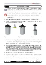
Page 44: ...the maximum level alarm E1 Now having checked the alarm is not caused by other anomalies see chapter 6 Diagnostics carry out replacement as indicated below NEVER REPLACE THE CYLINDER WITH THE MACHINE...

Page 45: ...ow CODE M2 L1 U V L2 M1 W U M2 L3 V M1 W 400UMCLCCU02 PHASE NEUTRAL PHASE NEUTRAL 400UMCLCCU01 PHASE 1 PHASE 2 PHASE 3 400UMCLCCU03 PHASE 1 PHASE 3 PHASE 2 PHASE 1 PHASE 3 PHASE 2 Connect the level se...

Page 46: ...acetic acid at 20 Carry out the same operation on the louvres of the lower filter During cleaning do not damage or scratch the coupling parts guaranteeing water seal like the seat of the O ring at th...

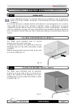
Page 47: ...tor inserting it into the air duct or in front of a fan unit where you want to put the steam directly in an environment without an air duct EXAMPLE OF DISTRIBUTION IN AIR DUCT The PEGO steam distribut...

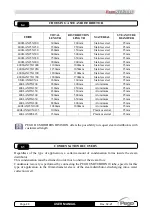
Page 48: ...80mm 200mm Aluminium 25mm 400LAN25X250 330mm 250mm Aluminium 25mm 400LAN25X350 430mm 350mm Aluminium 25mm 400LAN25X500 580mm 500mm Aluminium 25mm 400LAN25X650 730mm 650mm Aluminium 25mm 400LAN25X800 8...

Page 49: ...ity EMC 2014 30 EU LA CONFORMITA PRESCRITTA DALLA DIRETTIVA E GARANTITA DALL ADEMPIMENTO A TUTTI GLI EFFETTI DELLE SEGUENTI NORME THE CONFORMITY REQUIRED BY THE DIRECTIVE IS GUARANTEED BY THE FULFILLM...

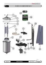
Page 50: ...Page 50 Rev 02 21 USER MANUAL ES OEM CCU SERIES SPARE PARTS 9 2...

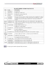
Page 51: ...nder for low conductivity with capacity 6kg h electrodes anti scale filter and O rings replacement kit 10 400HUMESDIS Display NANO EasySTEAM series 11 ES MINI CCU Cylinder Bracket 12 400UMIVALV Water...

Page 52: ...tina 6 b 45030 Occhiobello ROVIGO ITALY Tel 39 0425 762906 e mail info pego it www pego it AFTER SALES ASSISTANCE Tel 39 0425 762906 e mail tecnico pego it Distributor PEGO s r l reserves the right to...

Reviews: