AIR10-1420A Operation Manual
Project maintenance process
46
Table 13-5 attitude of operator replacing synchronous belt
J1
J2
J3
J4
J5
J6
Arbitrary
angle
0
°
90
°
0
°
90
°
Arbitrary
angle
Replacement process of J5 axis synchronous belt
Operate the operator to the attitude shown in Table 13-5.
Turn off the power to the control.
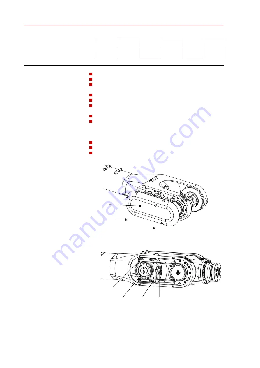
Remove the operator cover plate and four M4 screws, as shown in Fig.
13-10.
Loosen the timing belt adjusting screw
Remove four M4 screws from the motor base, as shown in Fig. 13-11.
Move the motor pulley assembly, remove the old synchronous belt and
install the new one
Install the motor base screw M4 preliminarily
The Allen wrench is equipped with adjusting screw to adjust the
synchronous belt to the appropriate tension; the frequency of
synchronous belt is 108-114hz, which can also be measured by pressure
method, with pressure g = 5N and deformation f = 2.55mm
Install the motor base screw M4 with the specified torque
Install the cover plate of the operator and apply sealant to the joint
Calibrate J5 axis of the operator
Fig. 13-9 removing the cover plate
Fig. 13-10 removing the timing belt
Cover plate
Screw M4
Mounting screws
Motor assembly
Synchronous belt Adjusting screw


