Scope of supply
MostraLog · Batteries (2 x AAA) · microSD-card · microSD adapter (1 x per
shipment) · Software for free download · Paper clip for device buttons
Accessories
IR remote control · External sensor incl. cable 2m or 5m · Alarm cable 1.8m
with open ends · Calibration set incl. boxes and calibration salts
Initial operation
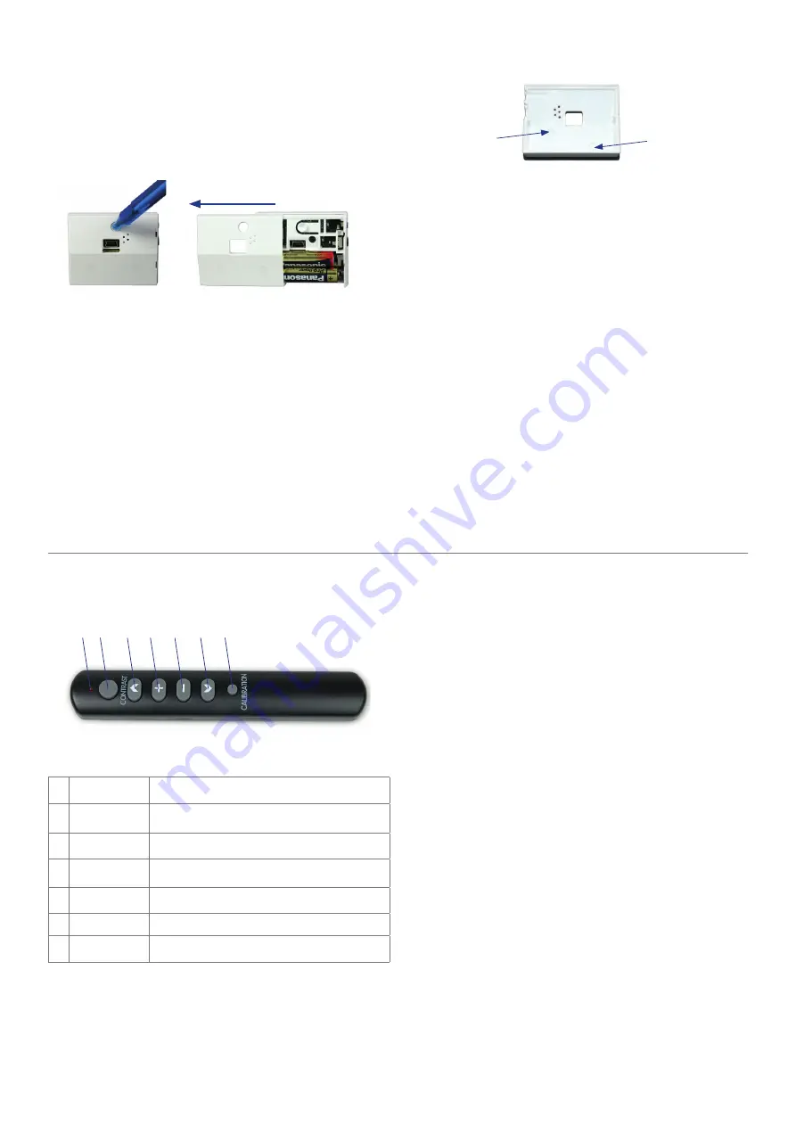
Use a pen (e.g. ballpoint pen) to open the device. Push the round button at
the back and simultaneously slide the back of the housing to the left. Putting
the thumb into the USB recess may help.
Insert 2 AAA batteries into the battery compartment. Ensure correct battery
position according to the battery position symbols.
If you want to use the recording function, insert a microSD-card into the card
slot in the direction indicated by the arrow, with the labelled side facing up.
Make sure that the card is inserted completely.
Note: Recording of the measured values starts automatically after insertion
of the microSD-card. The symbol
appears on the display. This may take
several minutes, depending on the selected measurement interval.
1. Push the locking button
2. Simultanously slide the back to the left
Wall mounting
To mount the device on the wall, use the notches provided in the lower
part of the rear of the device. The notches can easily be perforated, e.g. with
a small screwdriver. Use fl at head screws to avoid damage to the batteries.
All connectors (alarm, external temperature sensor and mini USB) and the
opening for the internal sensor should be freely accessible. Use a pen or
crochet hook to remove the device from the wall bracket.
Setup
Confi guration can be carried out using the buttons on the device, with the
IR remote control, or via PC software.
Confi guration on the device
Push buttons are located on the front of the device, left and right of the
IR sensor. To prevent tampering, the buttons can only be pressed with a
paper clip or similar tool. The left button corresponds to the remote control’s
button arrow up “
“. The right button corresponds to the remote control’s
“+“ button.
After 4 seconds without user input, the menu navigation aborts without
saving values and the display shows the current temperature and humidity.
Screw notch
Screw notch
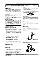
Confi guration with IR remote control
1 Function LED
Illuminates when a key is pressed
2 Contrast
Changes the LCD contrast
(See menu “LCD“)
3
▲
Move up in menu
4
+
Increase value +
5
-
Decrease value -
6
▼
Move down in menu
7 Calibration
Start calibration (see menu “CAL“)
Use the “
” and “
” buttons to scroll through the menu. The “+“ and “-”
buttons change settings.
The IR remote control detection time depends on the value of menu item “IR”.
1
2
3
4
5
6
7
Setup menu
MIN / MAX
Shows the measured minimum and maximum values since the last reset or
battery change.
RES - Alarm acknowledge (reset)
Confi rms an existing alarm, i.e. the device deactivates the alarm output. The
device reactivates the alarm output again as soon as the alarm limits are
exceeded. A delay time can be set in the menu item “DLY” to prevent the
device immediately triggering an alarm (e.g. when the show case is open).
CLK - Date and time setting
Date and time adjustment in the order: YR: Year, Mon: Month, Day: Day, HR:
Hour in 24h format, MIN: Minutes. Confi rm with button ”
“, the display
shows “OK“.
Note: The device has no time zone information. To ensure that the times in
the PC software are displayed correctly we recommend entering Coordinat-
ed Universal Time (UTC). The PC software automatically sets the device time
as UTC. Thus local times can be calculated if the device is used to document
international transports across time zones. The PC software automatically
displays local times, based on the UTC time of the device.
Coordinated Universal Time (UTC) is Central European Time (CET) minus 1
hour and Central European Summer Time (CEST) minus 2 hours.
ALM - Alarm
Defi nes the alarm limits. First set MIN/MAX temperature, then MIN/MAX
humidity. Confi rm with the “
“ button. The display shows “OK“. The active
alarm limits are saved on the microSD-card and preserved even during a
battery change.
DLY - Alarm Delay
Delays alarm trigger, e.g. during transport to the device’s destination or
while a show case adjusts to the desired climate. Select a value in hourly
increments and confi rm with the “
▲
“ button.


