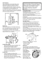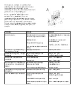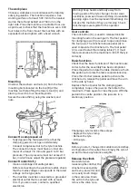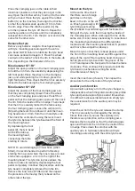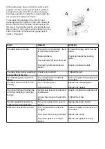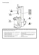
If the locking lever does not lock the vertical arm
properly or if the mounting head cannot be lifted
at least 2 mm above the rim, which is necessary
for proper operation, loosen the nut and adjust the
allen screw according to the figure.
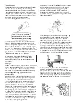
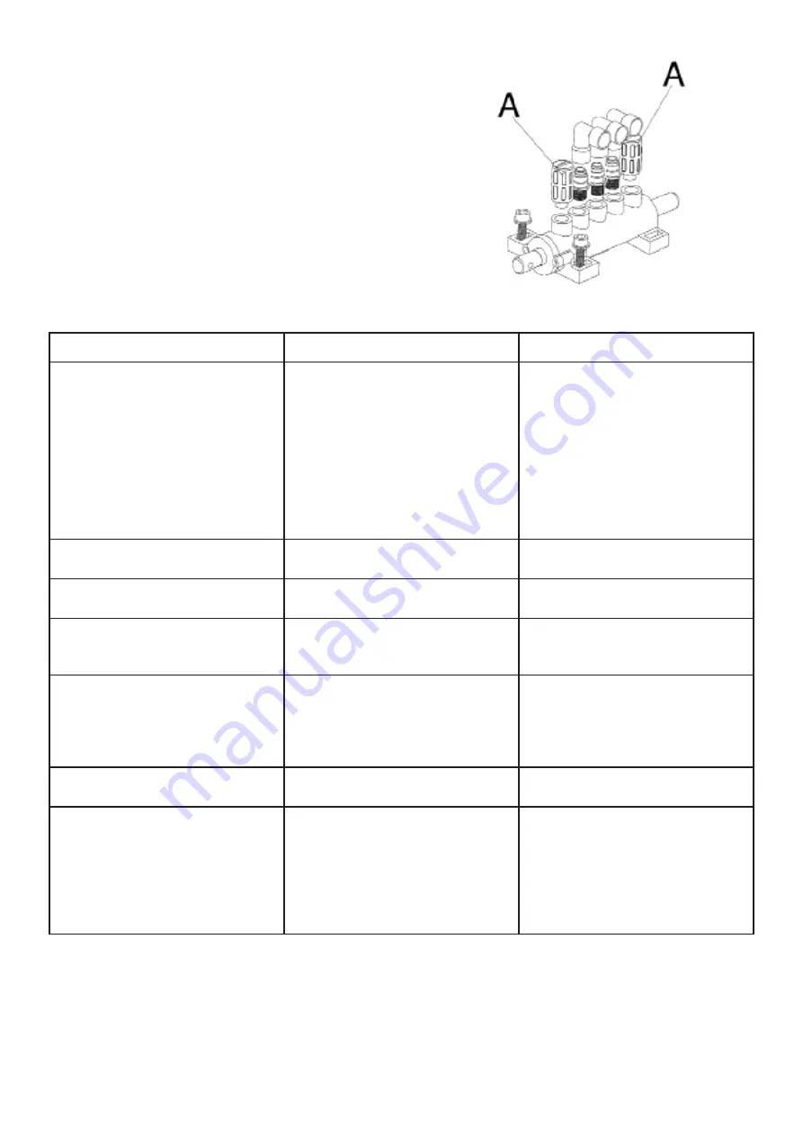
To maintain the reliability of the clincher and
clamping jaws, the mufflers on the valve should be
blown clean, remove the sheet metal cover on the
left side of the machine part by unscrewing the two
allen screws (5 mm). Remove the mufflers from the
valve. Clean with compressed air (purge gun) or
replace, if required.
Issue
Reason
Solution
The table does not rotate
The plug is not connected / there
is no power in the mains
Engine problem
The foot pedal (Z) does not work
The belt is poorly tensioned or
broken
Connect the plug / switch on the
power
Check and repair the rotating
table
Adjust or replace the belt
The table locks during assembly/
disassembly of the tyre
Poorly tensioned belt
Tighten the belt
The clamping jaws open/close
slowly
The compressed air muffler is
clogged with dirt
Clean or replace the compressed
air muffler
The table does not lock the rim
properly
Worn clamping jaws
Defective piston
Replace the clamping jaws
Replace the gasket
The mounting head touches the
rim when mounting / removing
the tyre
Spindle lock incorrectly adjusted
or defective
Loosen the screw on the spindle
lock
Adjust or replace the spindle lock
Tighten the screw
The foot pedal (V) and (U) are
locked in the wrong position
The return spring of the pedal is
broken
Replace the return spring
Difficult to activate the clincher
The compressed air muffler is
clogged
The valve stem’s O-ring is broken
The piston gasket or O-ring is
broken
Clean or replace the compressed
air muffler
Replace the O-ring
Replace the gasket or O-ring
Summary of Contents for 32836
Page 1: ...Tyre changer U 2011 D ckmaskin U 2011 Item No 32836...
Page 8: ...Varningsskyltarna...
Page 9: ......
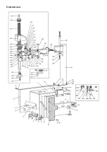
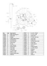
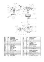
Page 16: ...Exploded view...
Page 17: ......
Page 18: ......
Page 19: ......
Page 20: ......
Page 21: ......
Page 22: ......
Page 23: ......
Page 24: ......
Page 25: ...Electrical circuit diagram...
Page 26: ...Pneumatic diagram...
Page 28: ......
Page 29: ......


