background image

Mount the balance shaft on the drive shaft with 

M10 x 150 bolt. Use a striking nutrunner (and a 

long H8 hex bit socket). If the balance axis is loose, 

there will be different measurement results.

The display is integrated with the machine.
NOTE! Use only your fingers to press the buttons. 

Never use the counterweight pliers or other poin

-

ted objects.

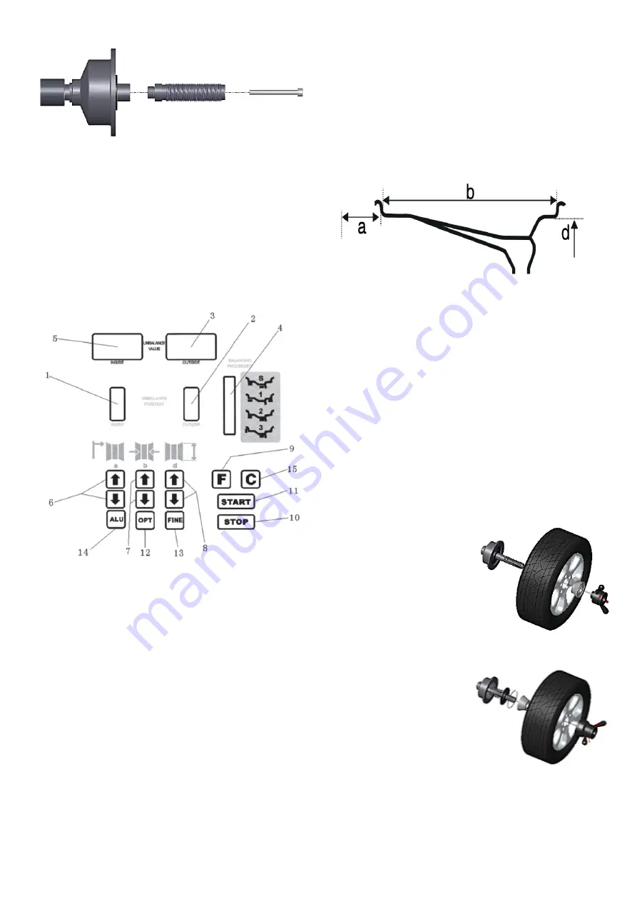
Display and control panel

1.  Indicator of the inside balance weight position.

2.  Indicator for the outside balance weight 


postion.

3.  The display shows the outside correction 

weight.

4.  Indicator for the adhesive weight position in the 

”ALU” position.

5.  The display shows the inside correction weight.

6.  Manual adjustment of the rim measured 


distance (a).

7.  Manual adjustment of the rim width (b).

8.  Manual adjustment of the diameter (d) on the 

rim.

9.  Selection of static or dynamic correction.

10. Stop button.

11. Start button.

12. Optimization of imbalance.

13. Shows exact unbalanced weight.

14. Program selection for aluminum rims.

15. Recalculation of the balance sheet weight.

Combination functions for buttons

F + C .................................................. Self-calibration
F + FINE .............................................. Self-diagnosis
F + STOP .................... Adjusting the protectivehood
F + (a-) + (a +) .............Dimensions in inches or mm
STOP + C ........................... Reset to factory settings

Rim parameters

Assembly and disassembly of wheels

Before mounting the centering cone on the balance 

shaft of the machine, check that the surfaces are 

on the centering cone and balance shaft are clean, 

no sand or dirt, and the tire is also clean. Remove 

any previous balance weights, check air pressure 

and that the rim is not damaged.
Then fit the appropriate centering cone.
Mount the wheel on the balance shaft and fasten 

with the quick nut.
Remember that poor centering leads to 


unnecessary imbalance.
Position of centering cone in most cases of 


aluminum rims. (To protect the rim on the outside 

against the quick nut).

Positive positioning is com

-

monly used. It works easily 

and is useful for 


different types of sheet me

-

tal rims and thin 


aluminum rims. Placement 

of centering cone in most 

cases of sheet metal rims.
Negative positioning is 

used to protect the inner 

hole of the rim and the 

main axle is positioned 

exactly even if the outside 

of the wheel is deformed. 

Used for all sheet metal 

rims, especially thick sheet 

metal rims. rims, especially 

thick sheet metal rims.

Disassembly of wheels
Release the quick nut by turning it 


counterclockwise and then release it with the red 

levers. Remove the cone and lift the wheel, being 

careful not to scratch the balance shaft..

Summary of Contents for 506799

Page 1: ...Automatic wheel balancer U 800 D ckbalanseringsmaskin U 800 Item No 506799...

Page 2: ...n som kommer att underl tta anv ndandet och underh llet av maskinen Tillverkaren tar inget ansvar f r personskador eller materiella skador som uppst r p g a att dessa instruktioner inte har f ljts sam...

Page 3: ...maskinen att arbetsomr det runt maskinen r fritt fr n f rem l som m jligen kan inneb ra fara samt att det inte finns olja eller annat klibbigt material p golvet som kan inneb ra fara f r anv ndaren S...

Page 4: ...n r rliga delar L st sittande kl der smycken och l ngt h r kan fastna i r rliga delar Var uppm rksam Se p det du arbetar med och anv nd sunt f rnuft vid anv nd ning av maskinen Anv nd inte maskinen o...

Page 5: ...mensioner i tum eller mm STOP C terst ll till fabriksinst llningar F lgens parametrar Montering och demontering av hjul Innan centreringskonan monteras p maskinens balansaxel kontrollera s att ytorna...

Page 6: ...ter skyddshuven och tryck p START knappen hjulet roterar N r det stannar b r b da dis playerna visa 0 Balanseringen r klar Balanseringsprocess och inmatningsmetod f r ALU 1 l ge Tryck ALU knappen s at...

Page 7: ...ta diametern dI p insidan AI tryck p d eller d f r att mata in v rdet di Anv nd hjulbreddsm taren f r att m ta diame tern dE p utsidan aE i f lgen tryck och h ll FINE tangenten och tryck p d eller d...

Page 8: ...ad precision Montera inte 100 grams vikten f re kalibreringen d tror datorn att den inte finns d r och all kalibrering r f rg ves blir det fel avbryt och g in i kalibreringsprogrammet fr n steg ett Va...

Page 9: ...med knapp b eller b f r att ka eller minska ljusstyrkan Tryck p a f r att spara informationen och g vidare Inch mm Som m ttenhet f r f lgar r tums vanligast Om man vill kan enheten f r systemet st lla...

Page 10: ...en dra ur stickproppen och ta bort huven Remmen skall kunna tryckas ca 4 mm ner t p mitten Justera genom att sl ppa p motorns monteringsskruvar och justera motorns l ge kontrollera s inte remmen glapp...

Page 11: ...saxeln 1 Positionsensorn trasig 2 Datorkort felaktigt 1 Byt sensor 2 Byt datakort Err 5 Skyddshuven r ppen 1 Skyddshuven r ppen n r du trycker p start 2 Skyddshuvens l gesomkopplare trasig 3 Datorkort...

Page 12: ...Reservdelslista...

Page 13: ......

Page 14: ......

Page 15: ...B 014 100251 0 Skruv 1 S5 PX 800 020300 0 Fotspak 1 S6 C 200 380000 0 Fj der 1 S7 PX 100 020400 0 Vevstake 1 S8 B 010 060301 0 Skruv 1 S9 B 040 061412 1 Bricka 1 S10 B 004 060001 1 Mutter 1 S11 PX 10...

Page 16: ...Funktionsdiagram...

Page 17: ...Blockschema...

Page 18: ......

Page 19: ...nformation that will facilitate the use and maintenance of the machine The manufacturer accepts no liability for personal injury or property damage that occurs due to that these instructions have not...

Page 20: ...king with the machine that the work area around the machine is free of objects that could possibly pose a danger and that there is no oil or other sticky material on the floor that could pose a danger...

Page 21: ...g jewelry and long hair can get caught in moving parts Attention Look at what you are working on and use common sense when using the machine Do not use the machine if you are tired or under the influe...

Page 22: ...mensions in inches or mm STOP C Reset to factory settings Rim parameters Assembly and disassembly of wheels Before mounting the centering cone on the balance shaft of the machine check that the surfac...

Page 23: ...e cap and press the START button the wheel rotates When it stops both displays should show 0 The balancing is complete Balancing process and input method for ALU 1 mode Press the ALU button so that th...

Page 24: ...inside AI press d or d to enter the value di Use the wheel width gauge to measure the diameter dE on the outside aE of the rim press and hold the FINE key and press the d or d key to enter the dE val...

Page 25: ...n Do not mount the 100 gram weight before calibration then the computer thinks it is not there and all calibration is incorrect it will be wrong to cancel and enter the calibration program from step o...

Page 26: ...a and select with button b or b to increase or decrease the brightness Press a to save the information and continue Inch mm As a unit of measurement for rims inches are most common If desired the uni...

Page 27: ...y pulling out the plug Check the belt tension pull out the plug and remove the hood The strap must be able to be pushed approx 4 mm downwards in the middle Adjust by loosening the engine mounting scre...

Page 28: ...ensor broken 2 Computer card incorrect 1 Replace sensor 2 Replace data card Err 5 The protective hood is open 1 The protective cap is open when you press start 2 The safety switch position is broken 3...

Page 29: ...Spare parts list...

Page 30: ......

Page 31: ......

Page 32: ...B 014 100251 0 Screw 1 S5 PX 800 020300 0 Foot lever 1 S6 C 200 380000 0 Spring 1 S7 PX 100 020400 0 Connecting rod 1 S8 B 010 060301 0 Screw 1 S9 B 040 061412 1 Washer 1 S10 B 004 060001 1 Nut 1 S11...

Page 33: ...Function diagram...

Page 34: ......

Page 35: ......

Page 36: ...Verktygsboden Erfilux AB K llb cksrydsgatan 1 SE 507 42 Bor s Verktygsboden Bor s Sweden 0120504 03...

Reviews: