the result by lowering the protective hood and
pressing the START key, the wheel spins, when it
stops, both side displays should show zero. The
balancing is complete.
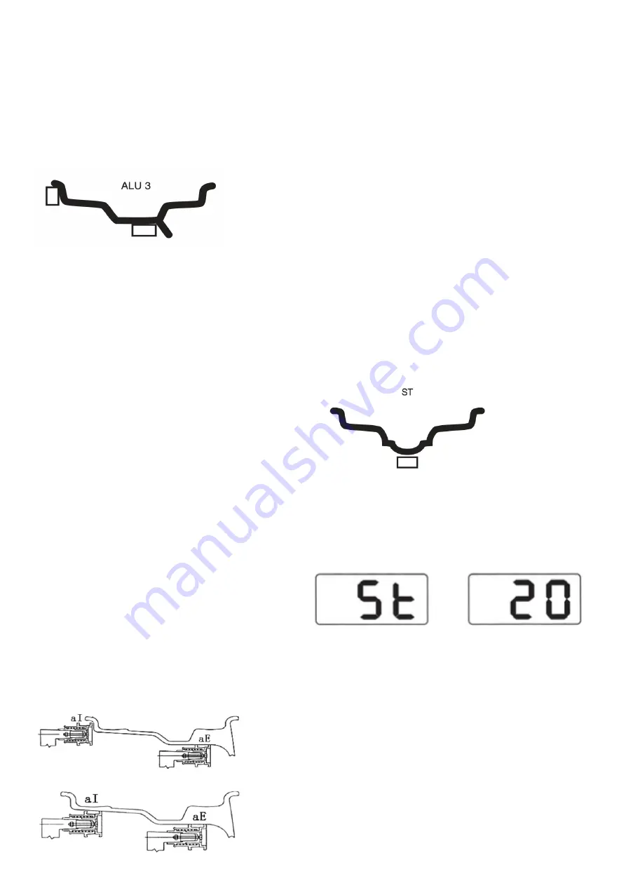
Balancing process and input method for ALU-
3 mode.
Press the ALU button so that the ALU-3 indicator
lights up.
Enter rim data, close the protective hood and press
the START button, the wheel rotates. When it has
stopped, the correction weights of the wheel are
shown on the displays, slowly rotate the wheel,
when all the diodes in the indicator for the inside
balance weight position light up, clamp the
corresponding correction weight at 12 o’clock on
the rim edge. Slowly rotate the wheel again, when
all the diodes in the outside balance weight
position indicator light up, paste the corresponding
correction weight at 12 o’clock on the rim. Check
the result by lowering the protective hood and
pressing the START key, the wheel spins, when it
stops, both side displays should show zero. The
balancing is complete.
Balancing process and input method for
ALU-S mode.
These three variants of ALU mode are not
suitable for all types of tires, and some tires cannot
be balanced with a good result. In this situation, the
ALU-S mode can be used. The data entry method
is as follows: Press the ALU button, until the ALU-S
LED lights up, pull out the dipstick to the inside of
the rim (aI) (the position you select there, paste the
balance weight on the inside). Press [a-] or [a +] to
enter the value ”aI”. When the dipstick has
registered the aI value, pull out the dipstick to (aE)
(the position you select there is to paste the
external balance weight) aE value, press [b-] or [b
+] to enter the value “aE”. Using the wheel width
gauge, to measure the diameter (dI) on the inside
(AI), press [d-] or [d +] to enter the value “di”.
Use the wheel width gauge to measure the
diameter (dE) on the outside (aE) of the rim, press
and hold the [FINE] key and press the [d-] or [d +]
key to enter the “dE” value. Rim data is entered,
close the protective hood and press the START
button, the wheel rotates. After stopping, the
displays show imbalance between the two sides.
slowly rotate the wheel, when all the diodes in the
inside balance weight indicator light are on, paste
the corresponding correction weight at 12 o’clock
on the inside of the rim. Slowly rotate the wheel
again, when all the diodes in the outside balance
weight position indicator light up, paste the
corresponding correction weight at 12 o’clock on
the outside of the rim. Check the result by lowering
the protective hood and pressing the START key,
the wheel spins, when it stops, both side displays
should show zero. The balancing is complete.
Static balance (ST)
ST position is only suitable for rims, where the
balance weight can be attached centered on the
rim, such as a motorcycle rim.
In normal mode, measure the diameter ”d” on the
rim, then press [d +] or [d-] to enter the value ”d”.
(”A” and ”b” can be random value). Press [F] to
enter ST mode. Close the protective hood and
press the START button, the wheel rotates.
After stopping, the left display shows ST, the right
display shows the imbalance weight slowly rotate
the wheel, when all the diodes in the indicators for
inside and outside balance weight position light up,
the adhesive correction weight at 12 o’clock
centered on the rim. Check the result by lowering
the protective hood and pressing the START key,
the wheel spins, when it stops the display should
show zero. The balancing is complete.
Conversion
Sometimes you can balance a tire and afterwards
find out that the rim data is not correct. Then you
do not need to perform the balancing again, just
press C (conversion) and enter new data.
Summary of Contents for 506799
Page 1: ...Automatic wheel balancer U 800 D ckbalanseringsmaskin U 800 Item No 506799...
Page 12: ...Reservdelslista...
Page 13: ......
Page 14: ......
Page 16: ...Funktionsdiagram...
Page 17: ...Blockschema...
Page 18: ......
Page 29: ...Spare parts list...
Page 30: ......
Page 31: ......
Page 33: ...Function diagram...
Page 34: ......
Page 35: ......


