background image

Assembly

1.  Disconnect the tyre changer from the power 

supply and air source.

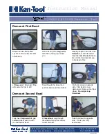
2.  Mount the 066 auxiliary arm to the 


corresponding position on the machine body 

in the ”1” area with the suitable bolt. (reserved 

mounting hole)

3.  Connect the air hose to the corresponding joint 

through the back hole of the body.

Usage

Assembly and disassembly of large flat tyres is a 

difficult job. With the help of 066, the arm helps to 

mount/dismount the tyre from the tyre clutch and 

makes the operation easier. This is a good help for 

the tyre changer.

Fit the tyres

Loosen the clamp according to the manual. 


Squeeze the tyre from the outside, tighten the 


corresponding pedal to open the hooks. Place the 

tyre on the mounting table. Press the 


corresponding pedal to close the hooks until they 

are close to the rim.

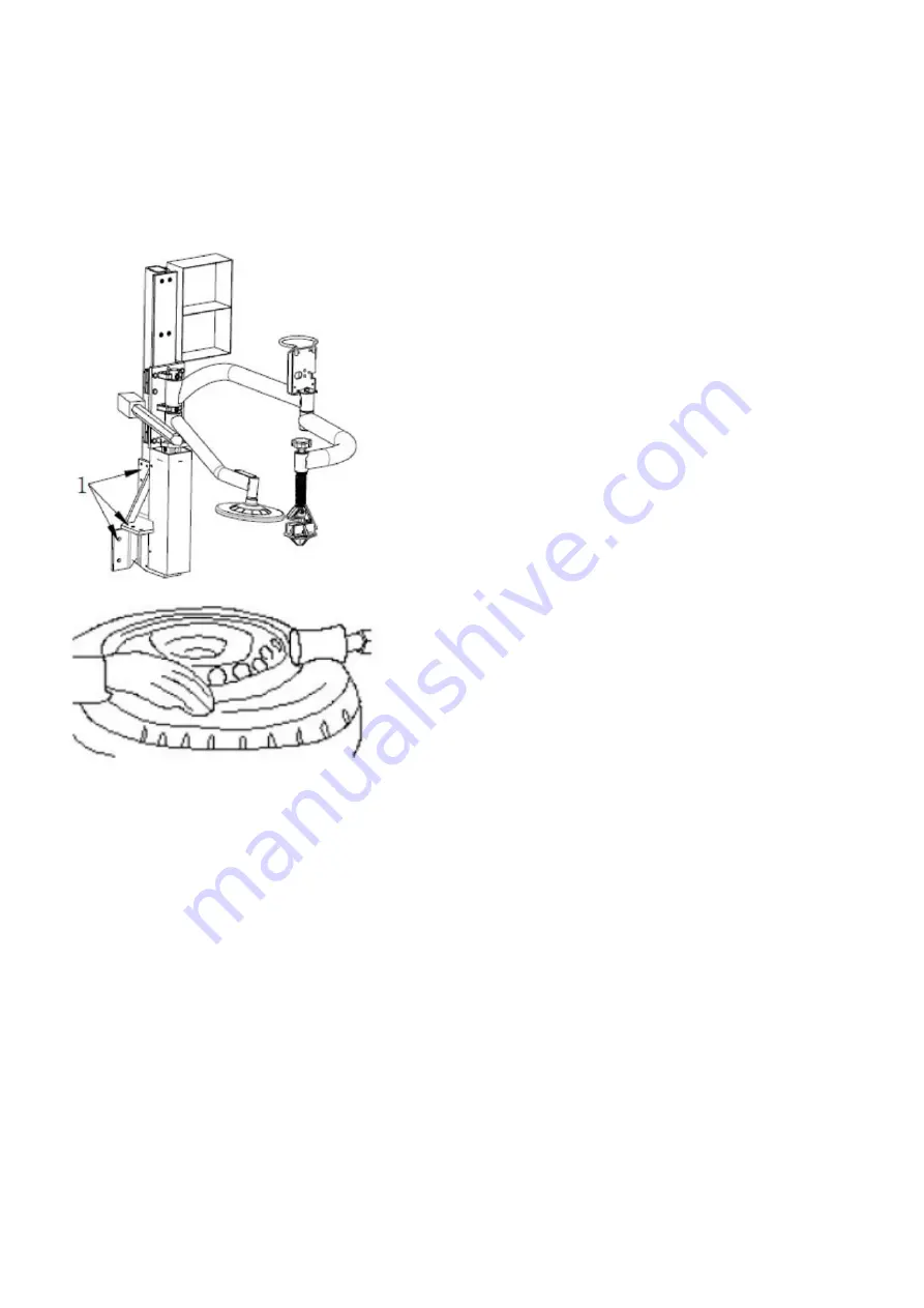
Disassembly of tyres

1.  Normally the tyre is tightly attached to the rim. 

Loosen the tyre with tyre weight rollers first, or 

use the clinch press. Pull the auxiliary arm 


above the tyre. Place the tyre weight rollers 


above the tyres so that they do not touch them. 

Lay down tyre weight rollers to push the tyre 

down. Press the pedal that rotates the 


assembly table. Loosen the clamp from the 

tyre.

Fitting the tyre

Lubricate the tyre clincher and turn the mounting 

table, mount the bottom clincher with the mounting 

head. Pull out the hexagon bar, press the upper 

clinch under the mounting head 5 mm with the 

tyre pressure roller, turn the rotating arm and move 

the tyre block above the tyre. Do not touch the rim 

during the operation, otherwise, it may cause 


damage to the rim due to friction. Press the 


pedal to rotate the assembly table and tyre 


pressure block, lower the auxiliary arm to press the 

tyre under the rim. Mount the tyre with the 


mounting head. Pay attention to safety during 

operation.

Pump the tyre

Important: It is very dangerous during the inflation 

operation, take it carefully and be aware that it can 

be dangerous if there are problems with the tyres 

or rims. The possible explosion causes a large 


force that can cause injury or death to the user.

Warning: Lubricate the tyre weight rollers (upper) 

and clinch before operation.

2.  Disassembly of the upper clinch

a) Move the mounting head near the edge of the 

rim, turn the tyre pressure lever to move the tyre 

pressure block above the tyre, press the shift lever 

to push in the tyre and insert the lift arm in the 

space between the tyre and the rim, then hang the 

clamp on the mounting head.

b) Raise the auxiliary lever, turn the tyre’s printhead 

in the opposite direction. Press the tyre with the 

shift lever to create enough space.

c) Press the pedal for the mounting table so that 

it rotates. With the help of the tyre’s print head, the 

upper tyre lock is released.

d) Raise the auxiliary arm to move the tyre press 

block to its working position.

3.  Disassembly of the lower clinch

Turn the tyre weight roller and move it under the 

tyre, but do not touch it with the rim. Press the 

pedal of the mounting table to rotate the table, 

meanwhile gradually lifting the auxiliary arm to 


loosen the tyre and disassemble the lower clutch.

Summary of Contents for 514019

Page 1: ...Tyre changer without a table Däckmaskin utan bord APO 3266 Item No 514019 ...

Page 2: ...då gäller inte garantin längre Om vissa delar är skadade var god ersätt dem enligt reservdelslistan OBS Garantin är ett år efter tillverkarens leveransdatum Garantin gäller inte de lättbrutna delarna Säkerhetsanvisningar 1 Placera inte händerna under monterings demonteringshuvudet under drift 2 Placera inte händerna mellan gapen under operationen 3 Placera inte händerna på däckets fälg när du demo...

Page 3: ...utrymme Placering och installation 1 Förberedelse av verktyg 2 Placera svänggångjärnen 3 på stammen 1 med 4 skruvar M12 träd luftslangen 2 genom hålet i pelaren Dra åt 4 låsmuttrar 8 3 Sätt bulten 9 i hålen i både pelare och den lutande cylinderarmen 11 dra åt den med en låsmutter 10 4 Skruva loss de två bultarna på det vänstra locket och ta bort locket anslut luftslangen 2 som tidigare nämnts til...

Page 4: ...att trycka pressen på däcket Repetera detsamma på flera punkter av däcket på båda sidor för att få loss klinchen från fälgen Att lossa däck från fälgen Se till att alla däckvikter har tagits bort från fälgen och att däcket är komplett tömt på luft innan du lossar däcket Lägg till smörjfett eller motsvarande smörjmedel på däckets klinch Om fett inte används kan maskinen skada däcket eller till och ...

Page 5: ... är en hjälpanordning för däckmaskiner den används för att avmontera och montera däck Innan någon operation av den här maskinen krävs uppmanas operatören att läsa igenom bruksanvisningen noggrant Låt bli att försöka göra operationer som inte anges i den Tillverkaren ansvarar inte för skador orsakade av felaktig drift Vänligen håll bruksanvisningen till hands för konsultation Teknisk data Arbetstry...

Page 6: ...taget för att skapa tillräckligt med utrymme c Tryck på pedalen för monteringsbordet så att det roterar Med hjälp av däckets tryckhuvud är den övre däckspärren lossad d Lyft hjälparmen för att flytta däckpressblocket till sin arbetsställning 3 Demontering av nedre klinchen Vrid däckviktsrullen och flytta det under däcket men rör inte det med fälgen Tryck på pedalen av monteringsbordet för att rote...

Page 7: ...karna så att de är öppna och stäng monteringsbordets pedal Trampa 3 4 gånger för att evakuera all tryckluft från maskinen Skadade delar måste bytas ut av professionella personer personer kan göra underhållet För att förlänga maskinens liv underhåll maskinen noggrant enligt bruksanvisningen Annars kommer det att påverka tillförlitligheten hos maskinen eller till och med skada operatören och andra i...

Page 8: ... till motorn Byt ut motorn Under montering av däcket låses inte bordet på plats Hakarna öppnas stängs långsamt Monteringsbordet låser däcket på plats på fel sätt 1 Luftläckage 2 Cylindern fungerar inte 3 Slitna hakar 4 Cylinderns tätningsringar har bryts 1 Kontrollera alla delar av tryckluftsystemet 2 Byt cylinderns kolv 3 Byt hakarna 4 Ersätt dem Monteringshuvudet rör alltid fälgen under monterin...

Page 9: ...id placeras inuti så vi lokaliserar sprängskissen enligt nedan Se siffran 12 i bilden hitta sedan alla meddelanden från listan och notera dem Som följande figur Notera informationen 3 Samla informationen om produkterna till exempel 4 Kontakta vår reservdelsavdelning för att bekräfta beställningsinformationen 5 Bekräfta att beställningsinformationen är korrekt så att beställningen med hänsyn till t...

Page 10: ......

Page 11: ...lace them according to the spare parts list NOTE The warranty is one year after the manufacturer s delivery date The warranty does not apply to the easily broken parts Safety instructions 1 Do not place your hands under the mounting disassembly head during operation 2 Do not place your hands between the gaps during the operation 3 Do not place your hands on the rim of the tyre when removing the ty...

Page 12: ...explosive area Location and installation 1 Preparation of tools 2 Place the swing hinges on the trunk with 4 screws M12 thread the air hose through the hole in the pillar Tighten 4 locknuts 3 Insert the bolt 9 into the holes in both the column and the inclined cylinder arm 11 tighten it with a lock nut 10 4 Unscrew the two bolts on the left cover and remove the cover connect the air hose 2 as prev...

Page 13: ...eral points of the tyre on both sides to release the clinch from the rim To loosen tyres from the rim Make sure that all tyre weights have been removed from the rim and that the tyre is completely deflated before loosening the tyre Add grease or equivalent lubricant to the tyre clamp If grease is not used the machine can damage the tyre or even cause it to break Attach the rim with the mounting ho...

Page 14: ...Auxiliary arm 066 is a helpful device for tyre changers it is used to remove and mount tyres Before any operation of this machine is required the operator is advised to read the operating instructions carefully Do not attempt any operations that are not listed in it The manufacturer is not liable for damage caused by incorrect operation Please keep the operating instructions on hand for consultati...

Page 15: ...rm and move the tyre block above the tyre Do not touch the rim during the operation otherwise it may cause damage to the rim due to friction Press the pedal to rotate the assembly table and tyre pressure block lower the auxiliary arm to press the tyre under the rim Mount the tyre with the mounting head Pay attention to safety during operation Pump the tyre Important It is very dangerous during the...

Page 16: ...the hooks down so that they are open and close the pedal of the mounting table Depress 3 4 times to evacuate all compressed air from the machine Damaged parts must be replaced by pro fessionals with spare parts provided by the manu do the maintenance To extend the life of the machine maintain the machine carefully according to the operating instructions Otherwise it will affect the reliability of ...

Page 17: ...ngine While fitting the tyre the table is not locked in place The hooks open close slowly The mounting table locks the tyre in place incorrectly 1 Air leakage 2 The cylinder does not work 3 Worn hooks 4 The cylinder sealing rings have been broken 1 Check all parts of the compressed air system 2 Replace the cylinder piston 3 Replace the hooks 4 Replace them The mounting head always touches the rim ...

Page 18: ...mple we have to buy skewers because the skewer is always placed inside so we locate the exploded view as below See the number 12 from the figure then find all messages from the list and note them As the following figure Note the information 3 Gather the information about the products for example 4 Contact our spare parts department to confirm the order information 5 Confirm that the order informat...

Page 19: ......

Page 20: ......

Page 21: ......

Page 22: ......

Page 23: ......

Page 24: ......

Page 25: ......

Page 26: ......

Page 27: ......

Page 28: ......

Page 29: ......

Page 30: ......

Page 31: ......

Page 32: ...Verktygsboden Erfilux AB Källbäcksrydsgatan 1 SE 507 42 Borås Verktygsboden Borås Sweden 0120504 03 ...

Reviews: