background image

Part 2- Tyre changer 

Specifications

Dimensions of the external locking rim..... 10 ~ 21 ”
Dimensions of the internal locking rim ..... 12 ~ 24 ”
Max. Wheel diameter ....................... 1040mm (41 ”)
Max. Wheel width ............................... 355mm (14 ”)
Working pressure ......................................... 8-10 bar
Power supply .........110V (1ph) / 220V (1ph) / 380V 

(3ph)
Optional motor power ............... 0.75 / 0.55 / 1.1 kw
Max. Rotating torque (turntable) ............... 1078 Nm
Overall Dimension ............................. 96 * 76 * 93cm
Noise level ......................................................... 75dB
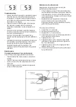
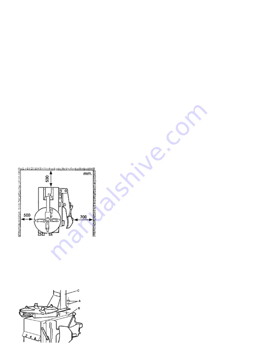
The workplace

Choose a workplace in accordance with statutory 

safety regulations. The machine requires a free 

working surface of at least 500 mm to the nearest 

wall on the left and behind and 700 mm on the right 

side. Place the machine on a stable and stable 

floor, use a spirit level to check that the machine 

is level. Drill four holes in the floor and mount the 

machine with an expander bolt and tighten.
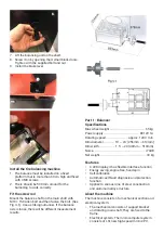
Installation

Unscrew the washers and nuts (A) from the four 

mounting bolts located on the top (B) of machines.
Get help lifting the tower stand (C) and placing 

it over the four mounting bolts. Secure the stand 

securely using the washers and nuts.

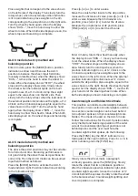
Connect to compressed air

• 

Fully depress the foot control (V) so that the 

clamping jaws do not open unintentionally.

• 

Connect compressed air to the tire machine. 

The connection hose must have an inner 


diameter of at least 7-8 mm, and give a 


pressure of 8 to 10 bar. The air pressure must 

not exceed 10 bar, in which case adjust the 


pressure regulator.

Connect to electricity

• 

Before connecting to the electrical outlet, check 

that the mains voltage corresponds to the rated 

voltage on the type plate.

• 

The machine must be connected to a grounded 

electrical outlet that is secured with at least, 

10A. If you are unsure, contact a qualified 

electrician.

Warning!

Keep hands and body away from moving parts of 

the tire machine. Do not wear necklaces, scarves 

or loose clothing. Unreadable warning signs shall 

be replaced immediately. Do not use the machine if 

they are missing. Check that the signs are 


readable for the operator.
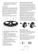
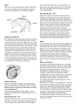
User controls

• 

The lock button (K), is used to release / lock the 

mounting head on the swingarm.

• 

The foot pedals for clamping jaws (V) are used 

to open and close the four jaws.

• 

The clincher release pedal (U) is used to 


operate the clincher arm.

• 

The foot pedal (Z) is used to start the 


rotating table (Y), it must rotate clockwise for 

the machine to tilt off the tire correctly.
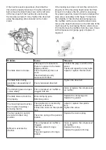
Basic functions

Check that the basic functions of the machine are 

correct after the installation has been completed. 

Press the pedal to rotate the table clockwise. Push 

the pedal up to rotate the table counterclockwise. 

Press the clincher release pedal to activate the 

clincher arm, release the pedal and move the arm 

to the side by hand. Depress the foot pedal for the 

clamping jaws completely, to open the jaws on the 

table to the maximum. Press again to close the 

jaws. With the pedal in the center position, the jaws 

are in a stationary position.

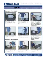
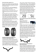
Changing a tire involves three steps:

• 

Depress the tire clamp.

• 

Disassembled tire

• 

Mounted tire

Summary of Contents for 498192

Page 1: ...Tyre changer balancer 2 in 1 D ckmaskin balanserare 2 i 1 Item No 498192...

Page 2: ...krare och fortare om maskinen anv nds till det den r konstruerad f r verskrid inte apparatens kapacitet F rhindra oavsiktligt start genom att bryta str mmen f re service och reparation eller n r mask...

Page 3: ...manipulera med maskinens s kerhetsanordningar Om s nd sker kan allvarlig skada eller olycka intr ffa Service reparation och reservdelar All form av underh ll och reparation skall utf ras av beh rig o...

Page 4: ...agare Glappar balansaxeln blir det olika m tresultat Del 1 Balanserare Specifikationer Max hjulvikt 65 kg Str mf rs rjning DC12V 1A Roterande hastighet ca 120r min F lgdiameter 10 24 256mm 610mm F lgb...

Page 5: ...om splittring Montering och demontering av hjul Innan centreringskonan monteras p maskinens balansaxel kontrollera s att ytorna p centreringskonan och balansaxeln r rena ingen sand eller smuts samt a...

Page 6: ...hjulet n r displayen visar RUN r r handen bort f r att l ta hjulet rotera D visar h ger display ST och v nster display statisk obalans se bild under N r hjulet slutar rotera rotera l ngsamt rotationsh...

Page 7: ...de Flytta skalan vidare inuti till aE positionen m t avst ndet aE v rde tryck p b eller b f r att mata in ett v rde M t f lgdiametern vid ett l ge tryck p d eller d f r att mata in dI v rdet M t f lgd...

Page 8: ...era hjul fr n balanseraren anv nd d ckv xlare f r att demontera d ck fr n f lg S tt p d cket p f lg f r att placera d ck och f lgm rken i samma position Optimera komplett Efter avst ngning och f re ba...

Page 9: ...eller b knappen f r att ndra niv er Tryck p a knappen f r att spara aktuell inst llning och ange n sta steg INCH och MM omvandlingsoperation De flesta f lgar har storlekar enhet INCH Om enheten r MM...

Page 10: ...om eln tets kabel ansluts tillf rlitligt Kontrollera om huvudaxelns pressade skruv r l s L smutter kan inte fixera hjulsp nningen p huvudaxeln Anv nd sexkantig skiftnyckel f r att dra t den pressade s...

Page 11: ......

Page 12: ...era p tryckregulatorn Anslut till el Innan anslutningen till eluttaget sker kontrollera att n tsp nningen verensst mmer med m rksp nningen p typskylten Maskinen skall anslutas till ett jordat eluttag...

Page 13: ...rdentligt fastl st vid bordet med hj lp av de fyra kl mbackarna Lossa vertikalarmen M med hj lp av spaken K och s nk den tills monteringshuvudet vilar 2 3 mm ifr n f lgen och d cksidan L s sedan fast...

Page 14: ...ran Lagring f rvaring Om d ckmaskinen inte skall anv ndas p en l ngre tid skall den kopplas ifr n n tsp nningen och kompressorn Sm rja in alla delar som kan rosta T m ur olja och t m vattenfiltret H n...

Page 15: ...det finns ingen str m i eln tet Motorproblem Fotpedalen Z fungerar ej Drivremmen r d ligt sp nd eller trasig Anslut stickkontakten koppla p str mmen Kontrollera och reparera det roterande bordet Juste...

Page 16: ......

Page 17: ......

Page 18: ......

Page 19: ......

Page 20: ......

Page 21: ......

Page 22: ......

Page 23: ......

Page 24: ...it is designed for Do not exceed the capacity of the appliance To prevent unintentional start up disconnect the power supply before servicing and repairing or when the machine is not in use Never leav...

Page 25: ...forbidden to remove or change the machine s safety devices If this still happens serious injury or accident can occur Service repair and spare parts All maintenance and repairs must be carried out by...

Page 26: ...ere will be different measurement results Part 1 Balancer Specifications Max wheel weight 65 kg Power supply DC12V 1A Rotating speed approx 120r min Rim diameter 10 24 256mm 610mm Rim width 1 5 20 40m...

Page 27: ...disassembly of wheels Before mounting the centering cone on the machine s balance shaft check that the surfaces of the centering cone and the balance shaft are clean no sand or dirt and that the tire...

Page 28: ...play shows RUN move your hand away to allow the wheel to rotate Then the right display shows ST and the left display static imbalance see picture below When the wheel stops rotating slowly rotate the...

Page 29: ...alue Move the scale further inside to the aE position measure the distance aE value press b or b to enter a value Measure the rim diameter at a position press d or d to enter the dI value Measure the...

Page 30: ...th flash use chalk to make a mark on the rim Remove wheels from the balancer use tire changers to remove tires from rims Attach the tire to the rim to place the tires and rim marks in the same positio...

Page 31: ...el is 4 Press the b or b button to change levels Press the a button to save the current setting and enter the next step INCH and MM conversion operation Most rims have unit INCH sizes If the device is...

Page 32: ...the mains cable is connected reliably Check if the main shaft pressed screw is loose Lock nut can not fix the wheel tension on the main axle Use a hexagon wrench to tighten the pressed screw on the ma...

Page 33: ......

Page 34: ...Connect to electricity Before connecting to the electrical outlet check that the mains voltage corresponds to the rated voltage on the type plate The machine must be connected to a grounded electrical...

Page 35: ...f the rim edge Then check that the rim is securely locked to the table using the four clamping jaws Loosen the vertical arm M using the lever K and lower it until the mounting head rests 2 3 mm from t...

Page 36: ...underestimate the danger Storage If the machine is not to be used for a long time it must be disconnected from the mains voltage and the compressor Lubricate all parts that can rust Drain the oil and...

Page 37: ...in the mains Engine problem The foot pedal Z does not work The drive belt is poorly tensioned or broken Connect the plug switch on the power Check and repair the rotary table Adjust or replace the dri...

Page 38: ......

Page 39: ......

Page 40: ......

Page 41: ......

Page 42: ......

Page 43: ......

Page 44: ......

Page 45: ......

Page 46: ...Verktygsboden Erfilux AB K llb cksrydsgatan 1 SE 507 42 Bor s Verktygsboden Bor s Sweden 0120504 03...

Reviews: