background image

YOU WILL NEED TO SUPPLY:

Ř

Cedar or Impervious shims/spacers (12 to 20)

Ř

2" galvanized roofing nails (1/4 lb.)

Ř

Closed cell foam backer rod/sealant backer  
(24 to 32 ft.)

Ř

Pella® SmartFlash™ foil backed butyl window  
and door flashing tape or equivalent

Ř

Pella Window and Door Installation Sealant or 
equivalent high quality, multi-purpose sealant 
(2 to 3 tubes per door)

Ř

Low expansion, low pressure polyurethane 
insulating window and door foam sealant  
- DO NOT use high pressure or latex foams 

Ř

Pella aluminum sill support or 2 x 4 wood blocking

Ř

Interior trim and/or jamb extensions (15 to 40 ft.)


FOR MULLION APPLICATIONS:

Ř

I bar joining connector

Ř

Pella silicone foam tape

Ř

Mullion end plug (2)

Ř

Field applied fins (4 pcs. per unit)

Ř

Head drip fin (Vertical Mullion applications only)

TOOLS REQUIRED:

Ř

Tape measure

Ř

Level

Ř

Square

Ř

Hammer

Ř

Stapler

Ř

Hacksaw

Ř

Sealant gun

Ř

Scissors or Utility knife

Ř

Screwdrivers

Ř

(#2 Phillips with 8" shaft and small 
flat blade)

Ř

Rubber mallet

Ř

Drill

Installation will require two or more 
persons for safety reasons.

4&"-"/5

4&"-"/5

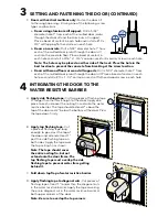
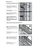
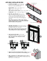
A. 

Confirm the opening is plumb and level. 

Ensure the bottom of the rough opening does 
not slope towards the interior.

Note: It is critical the bottom is level.

*OUFSJPS

"

*OUFSJPS

#

4th cut: 
Make a 6" cut up from 
each top corner at a 45

o


angle to allow the water 
resistive barrier to be lapped 
over the fin at the head of 
the door. 

1st cut

2nd cut

3rd cut

Water Resistive Barrier

1C

B. 

Confirm the door will fit the opening.

 Measure all 

four sides of the opening to make sure it is 1/2" larger 
than the door in width and height. Measure the width 
at the top, bottom and center. Measure the height at 
the far left side, the far right side and in the center.

Note: Solid wood blocking of 1-1/2" or more is 
required around the perimeter of the opening. 
Fix any problems with the rough opening before 
proceeding.

C. 

Cut the water resistive barrier.

1


ROUGH OPENING PREPARATION

1A

1B

1C

Summary of Contents for 803V0102

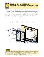
Page 1: ...e instructions and additional care Determining the appropriate installation method is the responsibility of you your architect or construction professional Sill Flashing Tape 2 Sill Flashing Tape 1 Water Resistive Barrier Sheathing Framing Nailing Fin Sill Support Top Flashing Tape Fin Corner Door Top Door Bottom Side Flashing Tape Interlocker Side Flashing Tape Corner Flashing Tape Corner Flashin...

Page 2: ...ealant gun Ř Scissors or Utility knife Ř Screwdrivers Ř 2 Phillips with 8 shaft and small flat blade Ř Rubber mallet Ř Drill Installation will require two or more persons for safety reasons 4 5 4 5 A Confirm the opening is plumb and level Ensure the bottom of the rough opening does not slope towards the interior Note It is critical the bottom is level OUFSJPS OUFSJPS 4th cut Make a 6 cut up from eac...

Page 3: ...ng to the exterior of the sill structure to support the edge of the door sill The sill support should be cut the entire length of the sill member and placed flush with the subfloor A Remove the plastic wrap and cardboard packaging from the door Note If screens or hardware are removed from the door at this time label them and store them in a protected area B OX XO doors only Remove the shipping space...

Page 4: ... end of the top nailing fin see inset These are used to hold the door in place while shimming it plumb and square C Plumb and square door Insert shims as necessary between the door and the sides of the rough opening starting up 6 from the bottom of the door Keep shims back 1 2 from interior face of window Note DO NOT shim above the door DO NOT OVER SHIM Interior 3C JYFE 1BOFM 1SF ESJMMFE QBOFM SFUB...

Page 5: ... overlap the top corners YUFSJPS YUFSJPS YUFSJPS F Doors with vertical mullions only Fasten the door sill to the rough opening sill using one of the following screw types and locations a Doors using aluminum sill support Drill a 5 32 diameter hole 1 from each of the mulled door jambs through the door sill and the aluminum sill support Place a bead of sealant in each hole and install a 10 x 3 4 sel...

Page 6: ...t operate correctly check to make sure it is still plumb level square and that the sides are not bowed If adjustments are required remove the foam with a serrated knife Adjust the shims and reapply the insulating foam sealant Note If the optional Patio Door High Performance Panel Retainer was ordered with the sliding door install the high performance roller retainer before installing the vent pane...

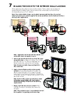
Page 7: ...ng building components and priming requirements C Shape tool and clean excess sealant When finished the sealant should be the shape of an hourglass Note This method creates a more flexible sealant line capable of expanding and contracting When applying siding brick veneer or other exterior finish material leave adequate space between the door frame and the material for sealant Refer to the illustrati...

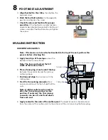
Page 8: ...et may be used to drive the I bar joining connector into position If necessary the I bar joining connector can be cut in half and driven from each end E Apply sealant to the ends of the mullion joint The bead of sealant should extend from the center of the mullion joint to the exterior of the unit covering the foam plug A Align foot bolt to the strike then tighten the exposed screw B Slide the foo...

Page 9: ...te A rubber mallet may be used to drive the I bar joining connector into position F Apply a bead of sealant covering the mullion joint from the center of the I bar joining connector to the exterior G Apply a reinforcement plate at the head using the square notches to align the plate to the head frame screws in the 1 1 2 wide flat groove to the interior side of the frame H Secure the plate with 8 x ...

Page 10: ...om of the jamb fins SBNF SFDFQUPS MFH C Install the two side fins into the top of the frame jamb grooves located on the side frame members of the door Slide the fins into place Note Spray a solution of water and soap on the frame jamb grooves to reduce sliding friction D Install and slide the top fin into the frame head groove located in the top frame member Note The top fin must overlap the exter...

Page 11: ...cted to properly manage moisture Pella Corporation is not responsible for claims or damages caused by anticipated and unanticipated water infiltration deficiencies in building design construction and maintenance failure to install Pella products in accordance with Pella installation instructions or the use of Pella products in wall systems which do not allow for proper management of moisture within ...

Page 12: ...This page left blank intentionally ...

Reviews: