background image

AWNING/

CASEMENT

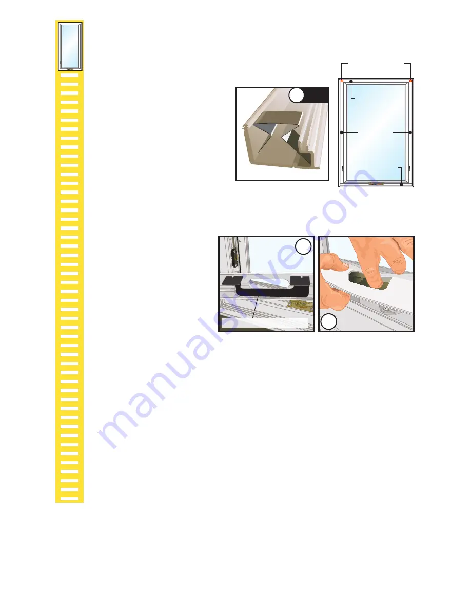
Re-install Interior Frame Covers.

Note:  Discard all Quick Release Bands before re-installing Interior Frame Covers.

I. 

Interior Frame Cover #3

 (Head cover on Casement, Fixed and 

Large Awning and the jamb cover without roto cover cut-out on 

Standard Awning units):


Starting on one end of the frame, 

insert the cover barbs of Interior 

Frame Cover #3 into the frame kerfs. 

Align the kerfs along the length of 

the cover and press until the cover 

"clicks" into place.

Note:  Interior Frame Covers #3 

contains compression springs which 

allow the cover to be compressed 

when re-installing Interior Frame 

Covers #1 in Step 4K.

4I

NOTE 

Compression Spring 

Compression Spring

location in 

Cover 3 

COVER 3

COVER 1

COVER 2

J. 

Interior Frame Cover #2

 (Sill cover on Casement, Fixed and Large Awning 

and a jamb cover with roto cover cut-out on Standard Awning units):


Place the cover support 

referenced in Step C4 inside 

the stop as shown. While 

holding the support in place, 

position the cover to align the 

cover barbs with the frame 

kerfs. Press the cover barbs into 

the kerfs while working toward 

the roto operator. Continue to 

hold the support in place to 

ensure proper placement of 

the support over the operator. 

Press the cover until it "clicks" into place.

Note:  The cover support bracket may need to be repositioned over the 

roto operator. The correct support position allows the cover barbs to be fully 

seated into the frame kerfs.

4J

Cover Support Bracket 

4J

K. 

Interior Frame Cover #1

 (Jamb covers on Casement, Fixed and Large 

Awning and the head and sill covers on Standard Awning units):


Insert the cover barbs of the first Interior Frame Cover #1 into the frame kerfs near 

Interior Frame Cover #2 first. Rotate the Interior Frame Cover #1 towards Interior 

Frame Cover #3 and align the kerfs along the frame, then press the cover until it 

"clicks" into place. Repeat on the other cover.

L. 

Insert the roto cover, crank handle and lock handle.


See steps at the end of the instructions.

Summary of Contents for 80YV0102

Page 1: ...ALLED EXTERIOR INSERT REPLACEMENT WINDOW EXISTING WINDOW EXTERIOR REMOVE EXISTING SASH and STOPS EXTERIOR Always read the Vinyl Window and Door Limited Warranty before purchasing or installing Vinyl W...

Page 2: ...e existing window frame and repair or replace any defective or rotted wood parts Remove or seat any nails B Clean the opening of any dirt debris or excess old paint before proceeding Chisel off any hi...

Page 3: ...ame cover removal steps are for Casement Standard Awning Fixed Awning Casement and Large Awning The steps are similar for each but the order in which covers are removed will vary depending on the wind...

Page 4: ...behind the cover While keeping tension on the tool pull the tool away from the frame to start releasing the cover barbs from the frame kerfs B3 Cross Section of Interior Frame Cover with Tool Placeme...

Page 5: ...of the cover Slide the tool over while pulling up on the cover Continue along the length of the cover until it is removed C4 C4 NOTE Cover support bracket AWNING CASEMENT D Remove Interior Frame Cove...

Page 6: ...les at the jambs and into the opening sides D Plumb and square the window Insert shims between the window frame and the rough opening at the anchor hole locations in the window frame Keep shims back 1...

Page 7: ...hole through the mullion plates at the factory drilled anchor holes prior to inserting screws 42 Frame Width Vent Fixed Casement Large Awning 42 Frame Width Vent Fixed Casement Large Awning Mullion p...

Page 8: ...g Mullion plate If Frame Width 42 top and bottom screws are optional Mullion plate 3 High Combination Vent Fixed Casement Standard Awning Large Awning Number of factory drilled fastener locations may...

Page 9: ...renced in Step C4 inside the stop as shown While holding the support in place position the cover to align the cover barbs with the frame kerfs Press the cover barbs into the kerfs while working toward...

Page 10: ...ealant O If additional installation holes are needed drill a 5 32 installation hole through both the interior and exterior walls of the frame Counter drill a 3 8 hole through the interior wall only of...

Page 11: ...ion and the rough opening Follow foam manufacturer s instructions C Insert jamb hole plugs provided into each screw hole for single hung and double hung units Interior Finish or Trim The space between...

Page 12: ...the crank handle onto the stud Unlock open window then close and lock window E Fold the crank handle down and check alignment of knob with the pocket Note You may need to adjust the crank position on...

Page 13: ...he cam and lever meet Interior B Stop removed to show the lever and cam C AWNING CASEMENT E Push the screwdriver against the lock cam and rotate the bottom of the blade toward the lock lever This will...

Page 14: ...lla products in accordance with Pella installation instructions or the use of Pella products in wall systems which do not allow for proper management of moisture within the wall systems The determinat...

Reviews: