Installation Guide: RE524XP Wireless to Wireless Translator™
Resolution Compatibles
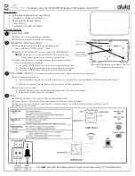
Wall mounting
screw locations
(Mounting hardware not included. Use two
#4 or # 6 screws for mounting )
Wall Tamper
(Do not overtighten
mounting screw)
Quick Setup
1
MOUNT AND WIRE
A
Select a mounting position and location.
B
Connect the power supply to the translator.
2
TRANSLATOR CONFIGURATION
A
Select the brand of panel that the translator must
talk to using the “PANEL SELECT” knob.
B
Set the “SENSOR SELECT” knob to position 7 (INSYNCTIVE).
NOTE:
This devices is for use with INSYNCTIVE sensors only.
Other sensor select protocols are not supported.
C
Sensor configuration: The translator must learn the sensors that
are to be translated or repeated.
a) Press the “CONFIGURE” button to enter configuration mode.
b) Tamper or trip all sensors that are to be included in the system
c) Press the “CONFIGURE” button to exit configuration mode
.
3
PANEL ENROLLMENT
(For full sensor enrollment instructions, refer to Advanced Setup, step 3)
A
Enroll Translator into Panel.
• Trip the translator tamper to enroll the translator into the panel (For Honeywell® and 2GIG® panels select loop 1).
-or-
• Enter ID into panel. The translator’s ID is printed on the bar code label.
B
Enroll Sensors into Panel
• With the translator cover open, trip each sensor to enroll it into to the panel.
• Finish setup of each sensor at the panel.
4
FINISH
A
With the translator cover open, perform a panel sensor test.
B
Close the cover. Test and verify proper operation of the sensors at the panel.
C
Cut the lock wire to lock the translator (For more information on locking, refer to Advanced Setup, step 4).
D
Secure cover with screw.
Features
• Selectable wireless panel compatibility
• Translator or repeater operation
• Rechargeable backup battery
• Cover tamper
•
Certified to UL1023, ULC1023


