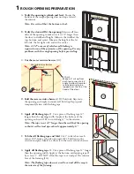
Note: Pre-drilling the additional holes in the fin at the interlocker
will make installation easier and will help prevent damage to the
fin. Use a 3/16" drill bit to pre-drill the holes.
&YUFSJPS
Î
C.
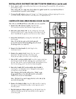
Fasten the door to opening
:
3C
High Performance
Screw Placement
2" 2" 2" 2"
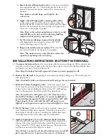
A.
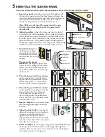
Apply side flashing tape.
Cut two pieces of flashing tape 4"
longer than the frame height of the door. Apply one piece to
each side over the nailing fin and onto the water resistive barrier.
The tape should extend 2" above the top of the door and 2"
below the bottom of the door. Press the tape down firmly.
&YUFSJPS
{
B.
Apply top flashing tape.
Cut a piece of flashing tape long
enough to go across the top of the door and extend at least
1" past the side flashing tape on
both sides. Apply the tape over the
top nailing fin as shown. Press the
tape down firmly.
Note: The tape should cover the
entire nailing fin, but not
extend onto the door frame.
The top flashing tape must
overlap the side flashing tape
to prevent water from getting
behind it.
&YUFSJPS
{
&YUFSJPS
{
{
4PMJEXPPECMPDLJOH
UIFFOUJSFMFOHUIPG
UIFTJMMNFNCFS
{
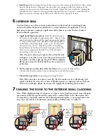
C.
Fold down top flap
of water resistive barrier (4C).
D.
Apply flashing tape to diagonal cuts.
Cut pieces of flashing tape at
least 1" longer than the diagonal cuts in the water resistive barrier.
Apply the tape, covering the entire diagonal cut in the water resistive
barrier at both upper corners of the door. Press the tape down firmly.
Note: Be sure to overlap the top corners (4D).
E.
Attach wood blocking
to the exterior of the opening to support the
edge of the door sill.
4
INTEGRATING THE DOOR TO THE WATER RESISTIVE BARRIER
Standard
Installation:
Beginning in the first hole from the
fin corner, drive 2" galvanized roofing nails into every other
pre-punched hole in the nailing fin. Drive four additional
nails through the head and sill fin at the fixed interlock
location. Space the nails 2" on center and position them so
there are two nails on each side of the interlocker. Drive the
nails until the head contacts the fin, however do not sink the
head. This will allow for movement of building material.
High Performance Installation
: Beginning in the first hole
from the fin corner, insert a #8 x 1-1/2" corrosion resistant
screw with a 3/4" outside diameter flat washer into every hole
of the installation fin. Drive four additional screws through
the head and sill fin at the fixed interlock location. Space the
screws 2" on center and position them so there are two screws
on each side of the interlocker. Drive the screws until the
head/washer contacts the fin, however do not sink the washer.
This will allow for movement of building material.


