background image

PV50b pellet burner


4/ 24 

Description


Specifications


DK9801A2 

www.pelltech.eu 


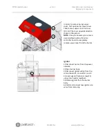
Table 1 Main components list 

No  Spare part code 

Short name 

Description 

1   

Burning chamber 

Pellets are burned inside the burning chamber on a 
grate. 

2   

Burner body 

The half of the burner that is located outside the 
boiler. Incorporates feed screw (internal auger), fans, 
controller etc. 

3   

User interface 

LCD screen, LED indicators and navigation buttons to 
show burner status and change settings. 

4   

Internal auger inlet  External fuel supply line (hose) is connected here. 

5   

Internal auger feed 
screw 

Transports pellets from inlet to the burning chamber. 
Internal auger is switched by controller board. 

6   

Burning chamber 
back wall 

Replaceable stainless steel wall that separates hot 
and cold surfaces and reduces heat transfer through 
boiler door. 

7   

Grates (set of two) 

Moving grates, where burning takes place. Air is 
supplied through holes in grates 

8   

Igniter 

Electric heating element to heat up air and ignite 
pellets in burning chamber. 

9   

Boiler connector 

Connector for power supply, flue gas fan, thermostat 

10   

Power supply 

AC-DC converter to supply internal controller board, 
feeder motor, fans and sensors. 

11   

Temperature 
sensor 

Internal auger temperature sensor to detect back 
burning before safety thermostat cuts mains power. 

12   

Battery 

Backup battery to enable safe shut down in case of 
mains power interruption. 

13   

Feeder motor 

Internal auger motor with rotation feedback to 
transport controlled amount of pellets to burning 
chamber. 

14   

Primary fan 


15   

External auger 
connector 

Quick connector to connect external auger. 

16   

Secondary fan 


17   

Controller board 

Electronic control unit to turn on/off burner, switch 
external auger, regulate combustion air supply etc. 

18   

Fuel level sensor 

Optical sensor to detect the presence of pellets in 
internal auger inlet. Normally, external auger is 
switched on, if no pellets detected. 

19   

Burning chamber 
cover 

Replaceable cover to increase combustion quality 

Summary of Contents for PV50b

Page 1: ...PV50b pellet burner User manual DK9802A2...

Page 2: ...1 Pellet storage 11 3 2 2 External auger 12 3 3 Electrical connections 13 3 4 Commissioning 13 4 Operation and maintenance 14 4 1 User interface 14 4 1 1 Status messages 16 4 1 2 Info menu 17 4 2 Sta...

Page 3: ...ilers liquid fuel solid fuel and universal boilers The PV 50b burner is connected to the boiler with a 90 mm flange similar to oil burners The burner is equipped with a safety thermostat a melting hos...

Page 4: ...W total width mm 240 W1 burner head width mm 168 Mass kg 17 Supply voltage VAC 220 240 Power max W 570 Power average W 25 40 Power at standby W 7 Noise dB 52 Emission class1 5 Operating temperature Co...

Page 5: ...supplied through holes in grates 8 Igniter Electric heating element to heat up air and ignite pellets in burning chamber 9 Boiler connector Connector for power supply flue gas fan thermostat 10 Power...

Page 6: ...PV50b pellet burner p 5 24 Description Specifications DK9801A2 www pelltech eu Figure 3 Burner main parts 1 2 3 4 5 6 7 8 9 10 12 13 14 15 16 17 18 11 19...

Page 7: ...The thickness of the boiler door must be less than 100mm The construction of the boiler must make it possible to open the door of the boiler with the burner connected and removing ash from the furnace...

Page 8: ...ng chamber For PV 50b minimum of 640mm is acceptable leaving L1 approx 380mm The height under the burner H1 should be enough for about 100mm of ash Minimum dimensions L and H for PV 50b L 640mm H 400m...

Page 9: ...ites DK9801A2 www pelltech eu Table 2 Mounting holes for boiler door Dimension Unit Value D hole for burning chamber neck mm 90 D1 flange bolt ring diameter mm 130 150 D2bolt holes mm 8 9 Figure 7 Mou...

Page 10: ...ve burning chamber from the burner body by loosening burning chamber bracket bolts 1 There is no need to completely remove brackets or bolts Figure 9 2 Remove upper grate 2 and then the lower grate 3...

Page 11: ...ing chamber the igniter end tip is at the same level with the back wall The tube of the inner auger must reach through its opening Caution After the installation of the burner always make sure that th...

Page 12: ...other object nearby with delivered chain Figure 12 shows correct position for external auger As the hose is a safety device it must be placed strictly as described below The vertical distance between...

Page 13: ...connections of the burner must be made by a qualified professional 3 4 Commissioning Before starting the burner for the first time please check that Burner body and burning chamber are securely conne...

Page 14: ...the burner Figure 14 User interface Up and down arrow keys enable to move up and down in menus also change parameter value in editing mode OK and back arrows have different actions depending on the c...

Page 15: ...PV50b pellet burner p 14 24 Operation and maintenance User interface DK9801A2 www pelltech eu Main menu in Figure 1Figure 15 can be accessed by pressing OK button Figure 15 Menu layout...

Page 16: ...auger and fan are working by Photocell must see the flame HOLD FLAME Boiler has reached an estimated temperature and boiler thermostat switched off pilot flame is held in the burning chamber BURN END...

Page 17: ...Burner from OFF to ON The display shows Waiting Now turn boiler thermostat to desired temperature The burner will go to Loading state If this is the first run external auger needs to be filled with p...

Page 18: ...m overheating It can take several minutes for the hot air to ignite pellets Signal from flame sensor marks the end on igniting and burner enters into PRE BURN status The purpose of this status is to a...

Page 19: ...ew fuel is added the external auger must be loaded again by switching burner OFF and back ON from menu Failing to do so will result Fuel error due to fuel loading timeout 4 5 Regular maintenance Follo...

Page 20: ...icture NOTE it may be necessary to remove user interface buttons from the controller board to completely remove upper cover from the burner Igniter 1 Disconnect burner from the power network 2 Open bu...

Page 21: ...801A2 www pelltech eu Battery 1 Disconnect burner from the power network 2 Open burner body 3 Disconnect battery wiring 4 Install new battery redo wiring redo burner cover and connect burner to the ne...

Page 22: ...heck burner temp from INFO menu check temp sensor connection check burning chamber and clean it check the chimney and pressure in the boiler check the internal feeder screw connection and rotation Ign...

Page 23: ...urner p 22 24 Problem and solutions DK9801A2 www pelltech eu No power No mains power Safety thermostat is turned off the power backburn check power connector cables check safety thermostat check burne...

Page 24: ...ical schematic DK9801A2 www pelltech eu 6 Annex A Electrical schematic Fuse Rating Description F1 3A Ignitor F2 2A Error pump F3 1A Auger F4 2A Fluegas fan F6 6A Fans and grate F8 1A Feeder F10 6A Bat...

Page 25: ...PV50b pellet burner p 24 24 Annex A Electrical schematic DK9801A2 www pelltech eu...

Reviews: