15
NORMAL OPERATION AND ALARMS
Normal Operation
During normal operation each control module will display the current gas
concentration on the display. If the sensor reading is below alarm level
then all the alarm relays and the visual alarm LED indicators on the front
panel should be off.
Alarms
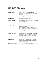
Each PT950-B control monitor is equipped with four (4) alarm relay
contacts. The alarms are labeled as Low, High & High-High. The fourth
alarm contacts is for sensor malfunction. The monitor activates the alarm
relays when the sensor reading exceeds the programmed alarm set point.
Also LEDs on the front panel will also light up for visual alarm indication.
Standard alarm set points are programmed at the factory before shipment.
The user must verify the alarm set points and make changes if desired.
Refer to section on Programming Alarm Set points.
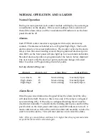
Factory Alarm Settings are:
Alarm # Alarm Level Alarm Type Contact Type
Low Alarm
10
Non-Latching Normally Open
High Alarm
15
Non-Latching
Normally Open
High-High
20
Non-Latching
Normally Open
Alarm Reset
Once the gas concentration has dropped below the alarm level the relay
will deactivate itself. However, this is true only of the relay is configured
as non-latching (NL). If the relay is configured latching then it must be
deactivated manually. To deactivate the latching alarm press and hold the
push button on the front panel until relays and LED indicators turn off. A
master alarm reset switch on the control module rack assembly can also be
used to reset the alarms. This will reset alarms on all control modules.
Note: If the gas concentration continues to be higher than the programmed alarm
set point the alarm will be activated again.


