WIRING
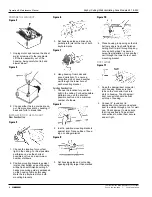
Figure 12
1. Wire unit following diagram above.
Run electrical cable as direct as
possible to unit. Do not allow cable
to touch sides or top of unit after
installation is complete.
Do not allow wires
to hang over edge
of scroll band.
Push all wiring up into corner of unit.
Wire left hanging over this edge will
become pinched or severed when
fan assembly is installed. Electrical
shock may result.
2. Replace fan assembly and secure
with sheet metal screw. Plug motor
into BLACK receptacle.
ATTACHING THE GRILL
Figure 13
1. Slide light reflector into front of grill
opening. Plug light into WHITE
receptacle. Place grill/reflector com-
bination over protruding screw, and
fasten into place using acorn nut
provided. HAND-TIGHTEN acorn
nut 1/4 turn after it is snug.
Figure 14
2. Install light bulb (100 Watt Max.).
Insert one tab on light lens into a
slot in the grill/reflector combination.
Squeeze other tab slightly and snap
into remaining slot.
Use And Care
Disconnect electrical
power supply and lock
out service panel before cleaning or serv-
icing this unit.
BULB REPLACEMENT
Remove lens by gently depressing sides
and pull down. Use 100 Watt maximum
incandescent bulb.
MOTOR LUBRICATION
The motor is permanently lubricated. Do
not oil or disassemble motor.
CLEANING
TO CLEAN LENS AND GRILL
Remove light lens and bulb. Remove nut
in center of reflector and lower assembly.
and reflector are
separate units. Unplug
light from white receptacle. Plastic
parts can be cleaned with mild, soapy
water (use a mild detergent, such as
dishwashing liquid) and dried with a soft
cloth. Do not use abrasive cloth, steel
wool pads, or scouring powders.
TO CLEAN FAN ASSEMBLY
Unplug fan assembly (BLACK recepta-
cle). Remove screw near receptacle and
lift fan assembly out. Gently vacuum fan,
motor and interior of housing. METAL
AND ELECTRICAL PARTS SHOULD
NEVER BE IMMERSED IN WATER.
Parts Replacement
If replacing parts, do so with properly
selected components which duplicate the
original parts correctly. Incorrectly sized
parts can damage the fan.
PARTS LIST
Refer to figure 15.
1. Plastic Lens
2. Acorn Nut
3. Bulb Holder
4. Light Reflector (Includes Keys 3 & 4)
5. Grill
6. Motor Plate
7. Fan Motor
8. Blower Wheel
9. Receptacle (Black)
10. Receptacle (White)
11. Housing
12. Damper/Duct Connector
13. Grounding Clip
14. #8 X 3/8" Screw
15. Motor Nut (2 are required)
16. Rubber Spacer (2 are required)
Operation & Maintenance Manual
Zephyr Ceiling/Wall Ventilating Fans Models ZL1 & ZL2
PENNBARRY 3
1401 North Plano Road, Richardson, Texas 75081
Phone: 972-234-3202
Fax: 972-497-0468
Figure 15


