16
ELECTRICAL WIRING
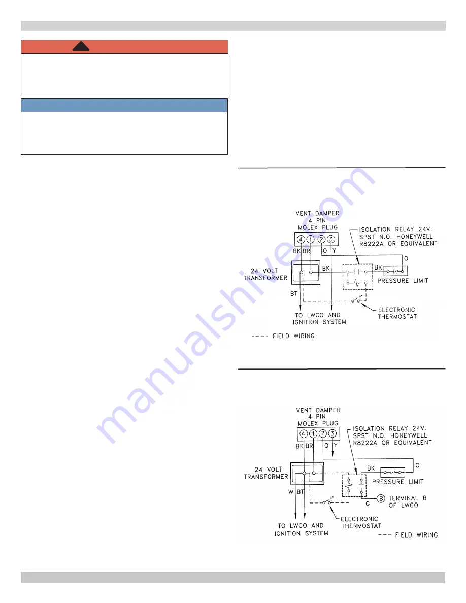
Figure 12a - Isolation Relay Wiring For Steam Boilers
With Float Type Low Water Cut Off And Use of
Electronic Thermostat
Figure 12b - Isolation Relay Wiring For Steam
Boilers With Probe Type Low Water Cut Off And Use
of Electronic Thermostat
WARNING
Electrical shock hazard. Turn OFF electrical power
supply at service panel before making electrical
connections. Failure to do so could result in death
or serious injury.
!
NOTICE
Label all wires prior to disconnection when servicing
controls. Wiring errors can cause improper and
dangerous operation. Verify proper operation after
servicing.
Electric Power Supply
Electrically bond boiler to ground in accordance with
requirements of authority having jurisdiction. Refer to
National Electrical Code, ANSI/NFPA 70.
Line Voltage Connections
A. Provide individual 120V, 15 amp circuit
(recommended) with fused disconnect or service
switch as required by authority having jurisdiction.
B. Locate a shut-off switch at the boiler.
C. Connect 115V electrical supply to primary leads on
24 volt transformer. Securely fasten with wire nuts.
D. Set heat anticipator at 0.6 amps for boilers
equipped with intermittent ignition. Connect 24
volt thermostat leads to two wires tagged “24 volt
thermostat” on boiler.
E. Boilers with 67D-1 float type low water cut-off, two
wires are black. One wire is located on secondary
of 24 volt transformer, second wire is located on
pressure limit control.
F. Boilers with CG400 probe type low water cut-off,
one wire is green and is located on terminal P2
of CG400 , second wire is black and located on
pressure limit control.
VENT DAMPER
Boiler is equipped with factory wired 4 pin molex harness,
that plugs into 4 pin molex receptacle inside vent damper
control.
Vent damper must be connected for boiler to operate.
Thermostat Installation
1.
Install thermostat on inside wall per manufacturer's
instructions.
2.
NEVER install thermostat on outside wall.
3.
Do not install thermostat where it will be affected by
drafts, hot or cold pipes, sunlight, lighting fixtures,
televisions, fireplace, or chimney.
4.
Check thermostat operation by raising and lowering
thermostat setting as required to start and stop
burners.
5.
Instructions for final adjustment of thermostat see
manufacturer's instructions.
Electronic Thermostats
A. Some electronic thermostats may lose their
memory or shut down. With probe type low water
cutoff, this may occur each time low water cutoff
detects low water condition. If this is the case, an
isolation relay is required for thermostat circuit. A
24 volt single pole single throw (SPST) normally
open (N.O.) relay is required, such as Honeywell
R8222A or equivalent. Wire as shown in Figure 12a
or Figure 12b.
B. Some electronic thermostats are not acceptable
for use with steam systems, check manufacturer
suggested use.
P/N 1305004, Rev. D [18/03/2015]


