background image

3


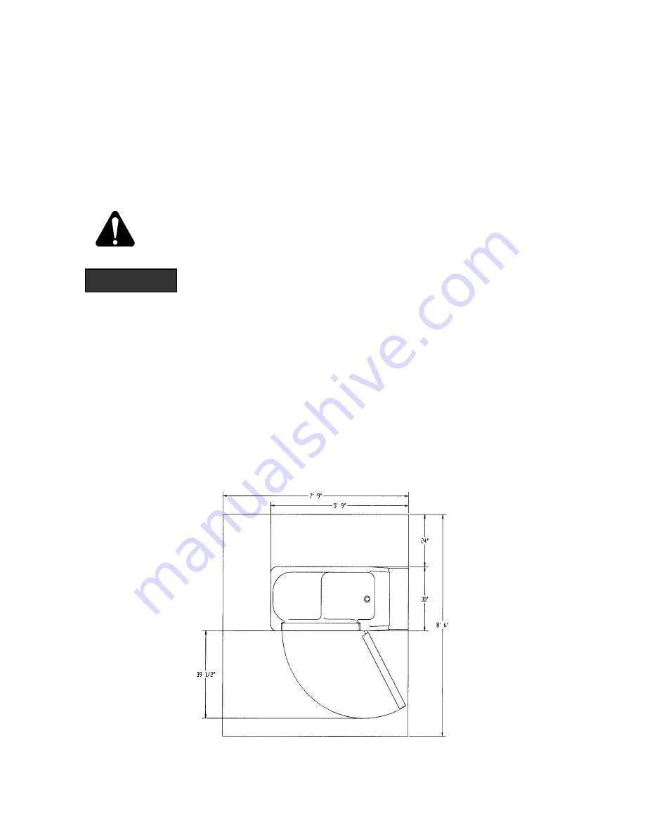
Figure 1

Introduction:


These instructions are for the installation of a Cascade Sit-Bath System 6900 Tub, 
Standard or Wide, with or without a Cascade Reservoir. The Reservoir is an optional 
accessory, which is to be pre-filled prior to placing the resident into the tub. Then the 
water in the reservoir can be released into the tub. This shortens the time required before 
the tub is full and the whirlpool can be started. 

 
Terminology and Symbols Meanings: 

When the terms “left” or “right” are used with reference to the tub, this means left or right 
as you look at the control panel from the seat end of the tub.  


 Meaning:  Safety warning. Failure to understand and obey this warning may 
result in injury to you or to others. 


Meaning:  Failure to follow these instructions may cause damage to 
parts or systems. 


Note: Refer to the “Tub Controls” section of this manual for the location of any of the 
controls referenced. 


Basic Room Dimensions: 

Figure 1 shows a room layout for a Standard Cascade tub without a reservoir. Figure 2 shows 
a room layout for a Standard Cascade with a Standard Reservoir. Figure 3 shows a Room 
layout for Standard Cascade with a Wide Reservoir. Figure 4 shows a Room layout for Wide 
Cascade with a Wide Reservoir. Figure 5 shows Room layout for Cascade with Reservoir 
side view. Figure 6 shows Room layout for End Opening Cascade with Reservoir side view. 


 CAUTION 


Summary of Contents for Cascade Aqua-Aire

Page 1: ...45 Revision F 02 04 08 1 866 PENNERS 1 866 736 6377 1 800 732 0717 E mail Address pennersales hamilton net Web Site www pennerpatientcare com Cascade End Opening Tub TUBS 360010 1 360010 1L 360010 1W 360010 X 360010 XL and 360010 XW 361910 1 361910 X 362010 1 362010 1L 362010 X 362010 XL RESERVOIRS 370000 1W 370000 1WL 370000 XW 370000 XWL Cascade Wide Tub ...

Page 2: ... AND COLD WATER SUPPLY REQUIREMENTS 7 ELECTRICAL REQUIREMENTS 7 UNPACKING THE TUB 7 UNPACKING THE RESERVOIR 8 TUB MODIFICATIONS FOR RESERVOIR 8 ASSEMBLING THE RESERVOIR 8 WATER SUPPLY HOSE CONNECTIONS 9 ANCHORING THE TUB RESERVOIR 9 WATER SUPPLY AND DRAIN CONNECTIONS 9 ELECTRICAL CONNECTIONS 10 FINISHING UP 11 TUB AND RESERVOIR CONTROLS 12 ...

Page 3: ...he seat end of the tub Meaning Safety warning Failure to understand and obey this warning may result in injury to you or to others Meaning Failure to follow these instructions may cause damage to parts or systems Note Refer to the Tub Controls section of this manual for the location of any of the controls referenced Basic Room Dimensions Figure 1 shows a room layout for a Standard Cascade tub with...

Page 4: ...4 4 Figure 3 Room layout for Standard Cascade with a Wide Reservoir Figure 4 ...

Page 5: ...5 5 Room layout for Wide Cascade with a Wide Reservoir Figure 5 Room layout Side View for Cascade with Wide Reservoir Figure 6 Room Layout Side View for End Opening Cascade ...

Page 6: ...s drain pipe is approximately 11 from the wall and 5 1 4 above the floor Figure 8 shows two different options for roughing in the drain pipe from the floor or from the wall Plumbing Requirements It is required that a licensed plumber make all plumbing connections He can select the best method of connection and if Reduced Pressure Zone Backflow Preventers are required ...

Page 7: ...SI Maximum supply Hot water temperature Consult local requirements for maximum allowed supply temperatures Not recommended over 120o F Electrical requirements The Cascade tub Aqua Air with reservoir is rated 7 25 amps at 120 Volts AC A 15 amp GFCI circuit is required The optional Cascade reservoir is rated at 75 amp and is connected to the tub s electrical box via hard wiring Unpacking the tub 1 R...

Page 8: ...cked with the reservoir The off white trim can be discarded 2 Remove the black hole plug located just above the overflow escutcheon by removing the plastic nut This plug and nut can be discarded 3 Replace the plug with the reservoir outlet fitting Gasket and outlet adapter These are packed with the reservoir See figure 9 for assembly order Ensure that the opening of the outlet fitting is pointed d...

Page 9: ... the tub reservoir in the final installation position The reservoir should be against the wall 2 Locate and mark on the floor the location of the tub anchoring points two 3 8 diameter holes in the return flange located inside the large access doors on the tub If installing a tub with reservoir there are also two anchoring points for the reservoir These are located in the return flanges just inside...

Page 10: ...it interrupter 1 Remove the covers from the electrical box of the tub and reservoir 2 For tubs with reservoirs connect the reservoir electrical supply lead to the tub s electrical kit a Remove the hole plug from the left side of the tub electrical box b Run the cable lead through that hole and secure using the cord restraint and nut provided c Connect the line wire to the line distribution bar loc...

Page 11: ... there is a sound like a running motor immediately switch OFF the circuit breaker Find the Aqua Aire button on the control panel of the tub and press it once Switch on the tub circuit breaker The motor should not be running now Finishing up 1 Once the tub reservoir has been connected to the drain checked for leaks and fixed if needed and is connected to power the access doors can be installed Warn...

Page 12: ...hower ON button The unit has a time adjustable automatic shut off 10 Hand shower sprayer 11 Aqua Air ON OFF button 12 Bath oil dispensing pump plunger 13 Shampoo dispensing pump plunger 14 Bath oil dispensing spout 15 Reservoir outlet 16 Shampoo dispensing spout 17 Drain plug cable 18 Reservoir fill lever 19 Reservoir fill on button 20 Reservoir fill off button On Reservoir equipped units only 8 9...

Page 13: ...r nearest distributor contact PENNER PATIENT CARE INC Box 523 102 Grant St Aurora NE 68818 1 866 PENNERS 1 866 736 6377 1 800 732 0717 E mail Address pennersales hamilton net Web Site www pennerpatientcare com ...

Reviews: