Doc
Ref:
EICT
Set-up
Guide
P201754
issue
5
January
2009
Insert connector of
PWM
card onto the vacant pins of header
JP2
. Monitor the
PWM
output (Terminal 5) with
respect to GND (Terminal 6) using an oscilloscope. Power up the
EICT/EICTM
. Check that output has 10-90%
duty cycle over the the required displacement of the transducer, adjust zero and gain trim pots if necessary.
(Equivalent to 0.5 to 4.5Vdc output).
Step 12 - Final setup
•
After configuration, switch off the power to
EICT/EICTM
. Remove DMM or oscilloscope connections.
Replace the lid using screws removed, ensuring all gaskets are present and in the correct place.
Recommended tightening torque for the lid screws is 2Nm.
•
Optional, but recommended - use an indelible pen to mark the configuration settings you have selected,
in the appropriate label area shown on the
EICT/EICTM
housing cover. (EICT type; Voltage output range [if
applicable]; transducer type)
•
The transducer and
EICT/EICTM
are now ready for use. Refer to
EICT/EICTM
technical data
sheet/brochure for full specification, mounting options and dimensions.
Additional Notes:
1
Current Module
(CM)
(4 - 20mA) and Pulse Width Modulation
(PWM)
'set-up' is unaffected by Dual
Supply option. Continue to follow set-up guide steps.
2
Recommended connections, but optional. Consult your Systems Engineer should other options be
required.
3
Make a note of, and check, the transducer cable colour codes (see Fig. 5) relative to the assigned
connector termination identities, to enable the
EICT/EICTM
to be correctly connected.
4
Cable diameter must be between 2.5 and 6.0mm diameter to maintain IP66 rating of the
EICT
housing.
Cable diameter must be between 3.0 and 8.0mm diameter to maintain IP68 rating of the
EICTM
housing.
Make off cable elements to the connector.
5
Rapid integrity check for connector and/or transducer.
EICT/EICTM
must be disconnected from the transducer to carry out following check!
Using a DMM, set to the resistance range: (See Fig. 5 for transducer cable colour coding)
i)
Measure between connector terminals assigned to transducer 'yellow' and 'blue'. Value should lie
between 40
Ω
and 170
Ω
.
ii) Measure between connector terminals assigned to transducer 'green' and 'yellow' and/or 'blue'.
Value should be 'open circuit'.
iii) Measure between connector terminal assigned to 'green' and the transducer body. Value should be
'short circuit'.
iv) 'Screen', if used - Connector terminal assigned to 'screen' should be 'open circuit' to all the other
connector terminations and transducer body unless otherwise specified by your Systems Engineer.
6
Any problems or questions should be e-mailed to sales@pennyandgiles.com
For technical assistance contact your local distributor or Penny+Giles at
UK
Tel: +44 (0)1202 409409
Email: sales@pennyandgiles.com
USA
Tel: +1 562 531 6500
Email: us.sales@pennyandgiles.com
Web:
www.pennyandgiles.com
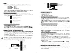
Fig. 6
A
B
Hz
OFF
OFF
1000
ON
OFF
310
OFF
ON
130
ON
ON
100
S1
ON
7 1
8 5
A B

