background image

Troubleshooting 7

Symptom

Possible Cause(s)

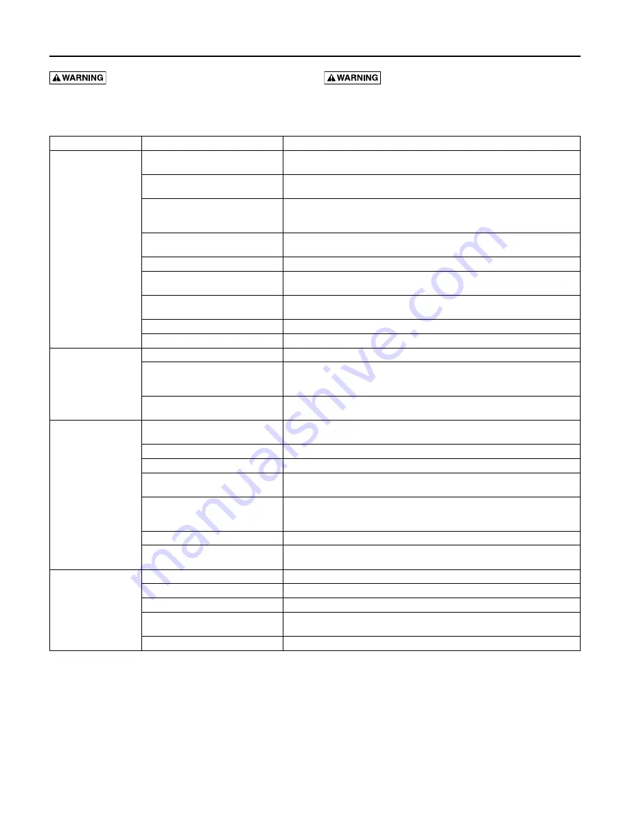
Corrective Action

motor not running

motor protector tripped.

allow motor to cool. make sure pump is completely submerged. clear debris from volute 
and impeller. check for high amp draw.

open circuit breaker or blown fuse.

replace fuse or reset breaker. If circuit breaker opens repeatedly, don’t reset it - call a 
licensed electrician.

Impeller clogged or binding.

check amp draw. If it is more than twice the nameplate amps, the impeller is locked. 
Bearings and shaft may be damaged. dIScoNNEcT PoWEr, clear debris from volute, 
impeller, and cutter as needed.

Power cable damaged.

resistance between power cable and ground should be infinity. If any reading is less than 
infinity, call a licensed electrician.

Bad control panel.

Inspect control panel wiring. call a licensed electrician.

defective liquid level switch.

With switch disconnected from power, check continuity through switch while activating 
liquid level switch. replace switch if necessary.

Not enough liquid in wet well to activate 
controls.

allow the liquid to rise several inches above the switch-on level.

Liquid level cords tangled

Untangle cords for free operation.

automatic controls defective

Try running pump in manual mode. If it runs, the automatic control is at fault.

Pump runs continuously

Liquid level control cords tangled

Untangle cords for free operation.

Pump is airlocked.

Stop pump for about one minute, then restart. repeat stopping and starting until the 
airlock clears. If the airlock persists, dIScoNNEcT PoWEr, pull the pump and drill a 
1/8” hole in the discharge pipe between the pump discharge and the check valve.

Flow in matches or exceeds the pump’s 
capacity.

a larger pump or more pumps may be needed.

Little or no effluent 
delivered from pump

check valve plugged, stuck shut, or 
installed backwards.

make sure check valve is installed correctly (flow arrow should point away from pump) 
and functioning correctly.

System head excessive.

consult dealer.

Pump suction plugged.

dIScoNNEcT PoWEr, pull pump, inspect, and clear as needed.

Wrong voltage or not wired correctly.

check pump’s rotation; check nameplate voltage against supply voltage (they must 
match); consult a licensed electrician.

Pump is air locked.

Stop pump for about one minute, then restart. repeat stopping and starting until the 
airlock clears. If the airlock persists, dIScoNNEcT PoWEr, pull the pump and drill a 
1/8” hole in the discharge pipe between the pump discharge and the check valve.

Worn or damaged impeller.

dIScoNNEcT PoWEr, pull pump and inspect impeller. replace if necessary.

Liquid level controls incorrectly installed 
or defective.

reposition or replace as necessary.

Pump cycles constantly

No discharge check valve installed.

Install discharge check valve.

discharge check valve stuck open.

repair or replace check valve as necessary.

Sewage wetwell too small.

consult dealer.

Liquid level controls incorrectly installed 
or defective.

reposition or replace as necessary.

Pump too small for inlet flow.

consult dealer about larger pump or second pump.

Troubleshooting

 Hazardous voltage. can shock, burn, or 

kill. disconnect power before attempting any service or 
repair work on pump.

 Hazardous impellers and unexpected starts 

which can cause loss of fingers. Keep hands away from 
pump suction inlet when working on or servicing pump.

Summary of Contents for HYDROMATIC SK60 Series

Page 1: ...èces Pour plus de renseignements concernant l utilisation l installation ou l entretien Composer le 1 888 957 8677 Français Pages 11 20 INSTALLATION AND OPERATOR S MANUAL SK60 Submersible Sewage Ejector Pump Installation et manuel de l opérateur Pompe submersible d eaux d egout SK60 269 Trillium Drive Kitchener Ontario Canada N2G 4W5 PH 519 896 2163 293 WRIGHT STREET DELAVAN WI 53115 WWW hydromati...

Page 2: ...sewage pump or a high water alarm See Troubleshooting in this manual for information about common sewage pump problems and remedies For more information see your retailer call Hydromatic customer service at 1 888 957 8677 or visit our web site at hydromatic com Hazardous voltage risk of electrical shock Shock can cause serious injury or death Failure to follow the warnings below can result in fata...

Page 3: ...ntenance as required 14 Drain all the liquid from the system before servicing California Proposition 65 Warning This product and related accessories contain chemicals known to the State of California to cause cancer birth defects or other reproductive harm Installation Thank you for purchasing this HYDROMATIC pump To help ensure years of trouble free operation please read the manual carefully Befo...

Page 4: ...sk of fire Do not pump flammable liquids Strong chemicals or salt water should not be pumped without consulting your Hydromatic distributor for proper seals and coatings Operation NOTICE Do not allow pump to run in a dry sump Doing so will void the warranty and may damage the pump An automatic overload protector in the motor will protect the motor from burning out due to overheating overloading Wh...

Page 5: ... in motor seal should be replaced Replacing seal Hold rotor On 3 phase motors only remove the impeller screw and impeller washer Unscrew impeller 13 Tap on end of shaft with plastic or rubber hammer This will push the rotating seal 10 from shaft and also push lower bearing from seal plate Clean seal plate 11 and motor housing 19 thoroughly All sand and dirt must be removed Remove stationary cerami...

Page 6: ... air lock use a small screwdriver to clear hole in the impeller cavity As a secondary precaution in installations of this type an 1 8 hole should be drilled in the discharge pipe just above the volute The check valve should be at least 12 inches above pump discharge and mounted horizontally Do not put check valve directly into pump discharge opening NOTICE In sumps where the pump is operating dail...

Page 7: ... hole in the discharge pipe between the pump discharge and the check valve Flow in matches or exceeds the pump s capacity A larger pump or more pumps may be needed Little or no effluent delivered from pump Check valve plugged stuck shut or installed backwards Make sure check valve is installed correctly flow arrow should point away from pump and functioning correctly System head excessive Consult ...

Page 8: ... 2 19103A043 9 Gasket 1 003240011 Ref Description Qty Part Number 10 Shaft Seal 1 014525A010 11 Seal Plate 1 068460002 12 Volute 1 068180002 13 Impeller 1 047810002 14 Screw 1 000300211 15 Diaphragm Switch 115V 20 STD 1 149740225 Diaphragm Switch 230V 20 STD 1 149740235 16 Switch Bracket 1 055020051 17 Capscrew 3 001010101 18 O Ring 1 000770031 19 Motor Housing 1 000565002 20 Handle 1 000600005 21...

Page 9: ...rvice will be accepted if received after the Warranty Period has expired This warranty is not transferable EXCEPTIONS Hydromatic Special Application Pumps Battery Back Up Sump Pumps Filtered Effluent Pumps Grinder Pumps and 2 1 2 Sewage Pumps are warranted for a period of 12 months from date of purchase or 18 months from date of manufacture whichever comes first HYDROMATIC SHALL NOT BE LIABLE FOR ...

Page 10: ... 1750 RPM three phase 6 10 HP polyphase 1750 RPM Intermittent Liquid Temperature 140 F 60 C Minimum Recommended Sump Diameter Simplex 24 609 6 mm Duplex 36 914 4 mm Automatic Operation Diaphragm pressure switch single phase only manual available Materials of Construction Class 30 cast iron Impeller Class 30 cast iron two vane nonclog Discharge Size 2 NPT 50 8 mm 3 NPT 76 2 mm optional Solids Handl...

Page 11: ...se d une pompe de puisard secondaire d une pompe de puisard de secours fonctionnant sur le courant continu et ou d une alarme de niveau haut d eau Se reporter au Tableau de recherche des pannes de cette Notice pour tout renseignement concernant les problèmes courants des pompes de puisard et comment y remédier Pour plus de renseignements s adresser au marchand de chez qui on a acheté la pompe ou a...

Page 12: ...s et bien éclairée enlever tous les outils et tout le matériel dont on ne se sert pas 9 Ne pas laisser les visiteurs s approcher de la zone de travail 10 Empêcher les enfants d accéder à l atelier en posant des cadenas un disjoncteur général et en enlevant les clés des démarreurs 11 Dissiper toute la pression du système avant d intervenir sur un élément 12 Si la conduite de refoulement de la pompe...

Page 13: ...rtiellement ou complètement immergée pour le pompage de liquides comme l eau La pompe prend en charge les corps solides sphériques jusqu à 5 cm de diamètre Cette pompe n a pas été vérifiée pour une utilisation en piscine Risque d inflammable Ne pompez pas de liquides inflammables Ne pompez pas de produits chimiques agressifs ou d eau salée sans avoir consulté votre distributeur Hydromatic concerna...

Page 14: ...tre changées AVIS Lorsque vous changez d échelle remettez toujours l appareil de mesure à zéro 0 avant d effectuer une mesure Si le fil est bon l aiguille de l ohmmètre s approche de zéro et ne bouge plus Si l aiguille de l ohmmètre ne bouge pas du tout le fil est coupé et doit être réparé ou remplacé Raccordez un des fils de l ohmmètre à un des fils du stator et à l aide de l autre fil de l ohmmè...

Page 15: ... la volute 12 avec des boulons 17 6 Avant de remplir le carter du moteur avec de l huile effectuez un test d étanchéité des joints Appliquez une pression d air de 3 à 3 5 kg au niveau du robinet à filetage NPT de 1 4 po 21 situé sur le dessus du couvercle du moteur et fermez le boîtier AVIS Une pression trop élevée endommagera le joint Le joint devrait alors être remplacé Plongez ensuite la pompe ...

Page 16: ...ème fonctionne librement La pompe est bloquée par de l air Arrêtez la pompe pendant une minute environ puis redémarrez la Répétez l arrêt et le démarrage jusqu à ce que le blocage par l air soit éliminé Si le blocage persiste COUPEZ L ALIMENTATION ÉLECTRIQUE tirez sur la pompe et percez un trou de 1 8 po 0 3 cm dans la conduite de refoulement entre le refoulement de la pompe et le clapet antiretou...

Page 17: ...103A052 Vis refoulement de 3 po 2 19103A043 9 Joint 1 003240011 Ref Description Qte Numéro de pièce 10 Joint d arbre 1 014525A010 11 Plaque d étanchéité 1 068460002 12 Carter de la volute 1 068180002 13 Impulseur 1 047810002 14 Vis 1 000300211 15 Interrupteur à membrane 115V 20 pi 1 149740225 Interrupteur à membrane 230V 20 pi 1 149740235 16 Support d interrupteur 1 055020051 17 Vis 3 001010101 18...

Page 18: ...Aucune demande de service en vertu de sa garantie ne sera acceptée après expiration de la durée de sa garantie Ces garanties ne sont pas transférables EXCEPTIONS Les pompes pour applications spéciales les pompes de puisard de secours à batterie les pompes d effluents à filtre les pompes broyeuses et les pompes d eaux d égout de 2 1 2 po Hydromatic sont garanties pendant une période de 12 mois suiv...

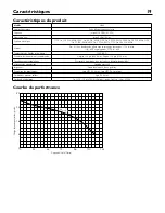
Page 19: ...in Température de liquide intermittente 140 F 60 C Diamètre de fosse minimal recommandé Simplex 24 po 609 6 mm Duplex 36 po 914 4 mm Fonctionnement automatique Pressostat à membrane une seule phase d emploi disponibles Matériaux de construction Fonte de classe 30 Impulseur Fonte de classe 30 deux palettes Dimension du refoulement 2 po NPT 50 8 mm 3 po NPT 76 2 mm opt Gestion des matières solides 2...

Page 20: ......

Reviews: