background image

P/N • Núm/Pte. • Réf. P/N 619408

4

Rev. A • Rev. A • Rév. A  6-5-01

WARNING

Be sure to keep the special pilot screw from this underwater light. This screw mounts and electrically grounds the housing
securely to the mounting ring and wet niche. Failure to use the screw provided could create an electrical hazard which could
result in death or serious injury to pool users, installers or others due to electrical shock.

3. Remove Junction Box cover, disconnect the light fixture wires, and pull the cord through the conduit.

4. Feed the new light fixture cord through the conduit from the niche to the Junction Box.

NOTE

Depending on the length of the conduit, special tools may be required to pull the cord through the conduit.

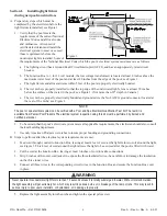
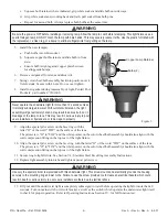
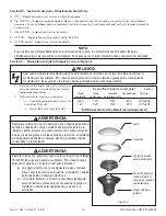
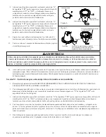
5. Leave at least 4 feet of cord to coil around the light fixture; see Figure 1. This 4 feet of cord coiled around the light

allows the light to be serviced after the pool is filled with water.

6. Cut the cord at the Junction Box, leaving at least 6 inches of cord to make connections.

7. Strip 6 inches of the outer cord jacket from the cord to expose the three insulated wires – be careful not to

damage the insulation on the three inner wires.

8. Connect all three wires to the corresponding circuit wires in the Junction Box (black wire to power, white wire to

common, and green wire to ground) and secure the Junction Box cover in place.

WARNING

Never operate this underwater light for more than 10 seconds unless it is totally submerged in water. Without total submersion,
the light assembly will get extremely hot, which may result in serious burns or in breakage of the lamp or lens. This may result in
serious injury to pool users, installers, or bystanders, or in damage to property.

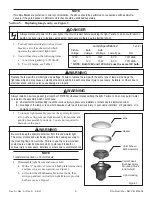
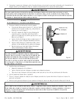
9. Replace light assembly into the niche and tighten the special pilot screw.

WARNING

Use only the special pilot screw provided with this underwater light. This screw mounts and electrically grounds the housing
securely to the mounting ring and wet niche. Failure to use the screw provided could create an electrical hazard which could
result in death or serious injury to pool users, installers or others due to electrical shock.

10.

Fill the pool until the underwater light is completely submerged in water before operating the light for more than 10
seconds. Turn on main switch or circuit breaker, as well as the switch which operates the underwater light itself,
to check for proper operation. Refer to Operating Instructions, Section IV., for full function test.

Section III. Switching Options for Spectrum Amerlite Color Synchronization.

A. Multiple SAm's ALWAYS in color synchronization.

1. If multiple SAm's are desired to always be on or off together and always with synchronized colors, multiple SAm's

may be controlled by a single switch to the extent allowed by code and capacity of the electrical equipment.

B. Multiple SAm's controlled separately but with color synchronize capabilities.

1. If on/off function or color of multiple SAm's is desired to be controlled separately, then SAm's should be controlled

by separate switches. It is recommended that the switches controlling SAm's be in immediate proximately of each
other to allow simple color synchronization.

Section IV. SAm Operating Instructions.

A. ON  --  SAm turns on whichever color it was turned off.

B. 1

st

 OFF/ON  --  SAm fast forwards to white and pauses for up to 30 seconds, waiting for other SAm's to synchronize.

SAm then begins rolling through the Spectrum and will continue rolling until receipt of next switch command.

C. 2

nd

 OFF/ON  --  SAm holds on displayed color.

D. OFF/ON  --  Repeats 1

st

 OFF/ON sequence function.

E. OFF/ON Again  --  SAm holds on displayed color.

Summary of Contents for SAm

Page 1: ...cal Code and all applicable local codes and ordinances Improper installation will create an electrical hazard which could result in death or serious injury to pool users installer or others due to electrical shock and may also cause damage to property Read and follow the specific instructions below Pentair Pool Products 1620 Hawkins Ave Sanford NC 27330 919 774 4151 10951 West Los Angeles Ave Moor...

Page 2: ...l or spa electrical system can be verified with a Pool and Spa Electrical Qualification Test Kit The test kit is available from Pentair Pool Products The electrical system inspection using this kit must be performed by trained and certified personnel 2 To be certain that the pool s electrical system meets all applicable requirements the electrician should also consult thelocalbuildingdepartment 3 ...

Page 3: ...e requirements of the National Electrical Code which the pool s electrical system must meet are as follows a The lighting circuit has a Ground Fault Circuit Interrupter GFCI and has an appropriately rated circuit breaker b The Junction Box or for 12 volt models the low voltage transformer is located at least 8 inches above ground level and at least 48 inches from the edge of the pool see Figure 1 ...

Page 4: ...ce light assembly into the niche and tighten the special pilot screw WARNING Use only the special pilot screw provided with this underwater light This screw mounts and electrically grounds the housing securely to the mounting ring and wet niche Failure to use the screw provided could create an electrical hazard which could result in death or serious injury to pool users installers or others due to...

Page 5: ...ing in death or serious injury to pool users installers or others due to electrical shock and may also cause damage to property WARNING Always install a new lens gasket part number 79101600 whenever disassembling the light Failure to do so may permit water to leak into the assembly which could cause a an electrical hazard resulting in death or serious injury to pool users installers or others due ...

Page 6: ...ult in serious injury to pool users installers or bystanders or in damage to property 9 Align the special pilot screw on the face ring with the letter O of the word TOP on the surface of the lens The pilot screw O in TOP and the white pointer on the color wheel bulb assembly should also align with the cord compression fitting on the top rear of the light fixture 10 Align the special pilot screw on...

Page 7: ...Ring Assy Instructions 1 Replace lens gasket A NEW LENS GASKET MUST BE USED EACH TIME THE LIGHT IS REASSEMBLED 2 With the light resting on its base place lens gasket assembly on light fixture and position so the white pointer on the color wheel bulb assembly points to the O in the word TOP on the surface of the lens See Figure 2 3 Align the special pilot screw on the face ring with the letter O of...

Page 8: ...P N Núm Pte Réf P N 619408 8 Rev A Rev A Rév A 6 5 01 Pentair Pool Products 1620HawkinsAve Sanford NC27330 919 774 4151 10951WestLosAngelesAve Moorpark CA93021 805 523 2400 This page is blank ...

Page 9: ...a con licencia o autorizado en conformidad con el Código Eléctrico Nacional y todos los demás códigos y reglamentos municipales La instalación incorrecta presenta peligro eléctrico con consecuencias de muerte o lesiones graves para quienes utilizan la piscina el instalador o demás personas debido a descarga eléctrica y puede asimismo causar daños a la propiedad Lea y observe las instrucciones espe...

Page 10: ...tema eléctrico mediante este juego debe ser efectuado por personal entrenado y autorizado 2 Para asegurarse de la conformidad del sistema eléctrico de la piscina con todos los requisitos pertinentes el electricista debe consultar asimismo el departamento de edificación municipal 3 Para asegurar la conexión de continuidad eléctrica y de puesta a tierra adecuada utilice únicamente nichos en húmedo d...

Page 11: ...ara subácuea Algunos de los requisitos del Código Eléctrico Nacional que el sistema eléctrico de la piscina debe cumplir son los siguientes a El circuito de iluminación debe contar con un interruptor de circuito de pérdida a tierra GFCI sigla en inglés por Ground Fault Circuit Interrupter y con un disyuntor con capacidad de desconexión adecuada b La caja de empalme o el transformador de bajo volta...

Page 12: ...e en posición la tapa de dicha caja ADVERTENCIA Nunca haga funcionar esta lámpara subácuea por más de 10 segundos a menos que esté totalmente sumergida en agua Al no estar totalmente sumergido el conjunto de la lámpara se pondrá sumamente caliente con graves quemaduras o rotura de la lámpara o del lente Ello podría provocar lesiones graves para quienes utilizan la piscina el instalador o las perso...

Page 13: ...usuarios de la piscina y demás personas debido a descarga eléctrica 1 Desactive el interruptor principal o el disyuntor así como también el interruptor que acciona la lámparasubácueamisma 2 Debe procurar los siguientes elementos a Una nueva guarnición para el lente No decatálogo79101600 b Dos 2 lámparas véase la Tabla 1 ADVERTENCIA Reemplace la lámpara con otra del mismo tipo y capacidad de vatios...

Page 14: ...olo de los pernos de la lámpara e Repita lo anterior con la segunda lámpara Reemplace siempreambaslámparasalmismotiempo ADVERTENCIA No olvide APAGAR la alimentación antes de instalar o quitar la lámpara Deje que la misma se enfríe antes de reemplazarla Este artefacto de iluminación utiliza una lámpara halógena de cuarzo NO toque la lámpara con las manos desnudas porque podría reducirse la vida úti...

Page 15: ...agua Para verificar el funcionamiento correcto active el interruptor principal o el disyuntor así como también el interruptor que acciona la lámpara subácuea misma Para la prueba funcional completa consulte la Sección IV Instrucciones de funcionamiento Sección VI Instruccionesparaelmontajedelarofrontaldeaceroinoxidable 1 Reemplacelaguarnicióndellente DEBEUTILIZARSESIEMPREUNAGUARNICIONDELENTENUEVAT...

Page 16: ...oma 3 79110600 Conjunto de aro frontal S S 4 79110400 Alambre unitensión 5 79112000 Perno 6 51008500 Arandela 7 98216100 Tuerca de latón 8 79111000 Conjuntodeabrazaderaconalambreunitensión 9 79100100 Lente SAm 8 3 8 pulg diám templado 10 79101600 Guarnición para lente de 8 3 8 pulg 11 79112400 Lámpara de 75 W EYC MR 16 NOTA SAm de 120 V tienen un transformador de 12 V integrado Todas las SAm utili...

Page 17: ...ution Ce luminaire sous marin doit obligatoirement être installé par un électricien agréé ou qualifié conformément au Code national d électricité et à tous les codes et règlements locaux en vigueur Toute mauvaise installation crée un danger électrique pouvant causer la mort par décharge électrique ou des blessures graves aux utilisateurs à l installateur ou à des tiers et pouvant également provoqu...

Page 18: ...r que les circuits électriques de la piscine sont conformes à toutes les normes en vigueur l électricien doit également consulter l instance locale responsable des travaux de construction 3 Pour garantir que les connections aux circuits régulateurs de tension et aux prises de terre sont effectuées de manière convenable utilisez uniquement les niches sous marines American Products B Étapes à accomp...

Page 19: ...oici quelques unes des normes du Code national d électricité que les circuits électriques de la piscine doivent respecter a Le circuit d éclairage comprend un disjoncteur de fuite de terre et un disjoncteur principal convenablement calibré b La boîte de raccordement ou pour les modèles à 12 Volts le transformateur à basse tension est situé e à une hauteur d au moins 20 cm au dessus du niveau du so...

Page 20: ...T N allumez jamais ce luminaire sous marin pendant plus de 10 secondes s il n est pas totalement immergé dans l eau Sans une immersion totale le luminaire chauffera de manière excessive ce qui peut provoquer des brûlures graves ou l explosion de l ampoule ou de la lentille Ceci peut entraîner des blessures graves pour les utilisateurs les installateurs ou tout spectateur ainsi que des dégâts matér...

Page 21: ...9101600 b Deux 2 ampoules voirTableau1 AVERTISSEMENT L ampoule de remplacement doit être de même type et de même puissance que l ampoule originale Tout manquement à cette consigne entraînera des dégâts dans le dispositif luminaire ce qui peut créer un danger électrique et entraîner la mort ou des blessures graves par décharge électrique pour les utilisateurs les installateurs ou des tiers et égale...

Page 22: ...remplacement un chiffon propre ouuneserviettedepapier 5 Installezla les nouvelle s ampoule s a Enfoncez les ampoules dans les douilles blanches b Pincez la fixation de cuivre de l ampoule et glissez l ampoule à l intérieur par le côté c Assurez vous que l ampoule est bien en contact avec la plaque de cuivre entre les butées de guidage 6 Retirezl ancienjointd étanchéitédelalentilleetjetez le 7 Abai...

Page 23: ...MONTAGEDUDISPOSITIF 2 Le luminaire étant posé verticalement sur sa base placez la lentille avec son joint d étanchéité sur le luminaire et positionnez la de telle manière que l indicateur blanc sur le bloc roue colorée ampoule soit dirigé vers la lettre O du mot TOP sur la surface de la lentille voir figure 2 3 Alignez la vis pilote spéciale de la bague extérieure face à la lettre O du mot TOP sur...

Page 24: ...lle caoutchouc captive 3 79110600 Bloc bague extérieure inox 4 79110400 Bride métallique à tension uniforme 5 79112000 Boulon 6 51008500 Rondelle 7 98216100 Écrou cuivre 8 79111000 Bloc bride métallique à tension uniforme 9 79100100 Lentille SAm diamètre 21 27 cm trempée 10 79101600 Joint d étanchéité pour lentille diamètre 21 27 cm 11 79112400 Ampoule 75 Watts EYC MR 16 NOTE Les SAm à 120 Volts s...

Reviews: