background image

AMERBRITE™ Color LED Pool Lamp Installation and User’s Guide

Be sure that the pool or spa meets the requirements of the current
National Electrical Code (N.E.C.) Article 680-22 and all local codes

and ordinances. A licensed or certified electrician must install the electrical system to
meet or exceed those requirements before the underwater light is installed. Some of
the requirements of the National Electrical Code which the pool’s electrical system
must meet are as follows:

The lighting circuit has a Ground Fault Circuit Interrupter (GFCI) for 120

VAC line voltage models, and has an appropriately rated circuit breaker.
The conductors on the load side of the GFCI circuit shall not occupy
conduit, boxes, or enclosures containing other conductors unless the
additional conductors are also protected by a GFCI. Refer to local codes
for complete details.

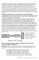
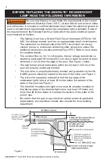
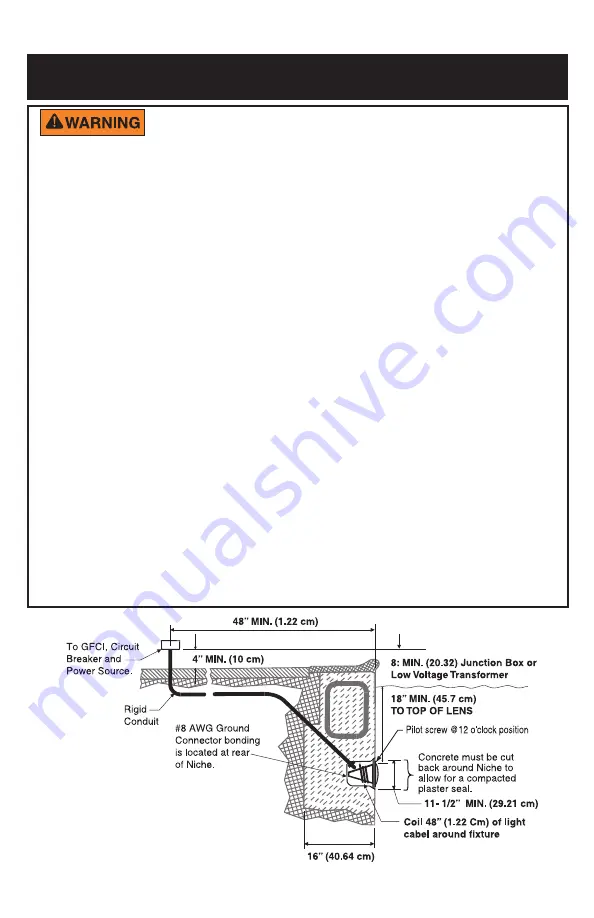
The Junction Box (or, for 12 volt models, the low voltage transformer) is

located at least eight (8) inches (20.3 cm) above water level and at least
48 inches (1.22 m) from the edge of the pool. See Figure 1 below.

The light fixture and all metal items within five (5) feet (1.524 m) of the

pool  are  properly  electrically  bonded.

The wet niche is properly electrically bonded and grounded via the No.

8 AWG ground connector located at the rear of the niche; see Figure 1.

The wet niche is properly installed so that the top edge of the

underwater light’s lens is at least 18 inches below the surface of the
water in the pool; see Figure 1.

The Amerlite

® 

Incandescent Light niche must be properly installed so

that the top edge of the Amerlite light’s lens is at least 18” below (not
more than 48 inches below in Canada) the surface of the water in the
pool or spa.

Be certain that the pool or spa electrical system meets all applicable

requirements, the electrician should also consult the local building
department.

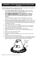
BEFORE  REPLACING THE  AMERLITE

®

  INCANDESCENT

LAMP  READ THE  FOLLOWING  INFORMATION

Figure 1

4

Summary of Contents for AmerBrite Underwater Color Changing LED Pool Lamp

Page 1: ...lation and User s Guide IMPORTANT SAFETY INSTRUCTIONS READ AND FOLLOW ALL INSTRUCTIONS SAVE THESE INSTRUCTIONS INSTALLATION AND USER S GUIDE AMERBRITE UNDERWATER COLOR CHANGING LED POOL LAMP FOR USE O...

Page 2: ...Multiple 12 VAC AmerBrite Lamps 1 Maximum Wattage Using Multiple AmerBrite Color LED Lamps with a 300W Transformer 1 Operating AmerBrite Color Lamps Using a Wall Switch 2 Powering on the AmerBrite Co...

Page 3: ...due to electric shock When installing and using this electrical equipment basic safety precautions should always be followed include the following RISK OF ELECTRICAL SHOCK OR ELECTROCUTION This underw...

Page 4: ...FCI should interrupt power Push the reset button Power should be restored If the GFCI fails to operate in this manner the GFCI is defective If the GFCI interrupts power to the light without the test b...

Page 5: ...de P N 521075 EasyTouch Control System User s Guide P N 521044 and SunTouch Control System User s Guide P N 520785 Using an External Transformer for Multiple 12 VAC AmerBrite Lamps When using a 300 Wa...

Page 6: ...tions of orange red and magenta tones 7 Royal Mode Richer deeper color tones 8 Blue Fixed color 9 Green Fixed color 10 Red Fixed color 11 White Fixed color 12 Magenta Fixed color 13 Hold Save the curr...

Page 7: ...elliBrite Lights Selecting a AmerBrite Light Color and Show Modes or Fixed Color Using an IntelliBrite Controller Using the IntelliBrite Color Light Controller AmerBrite lights are compatible with Int...

Page 8: ...x or for 12 volt models the low voltage transformer is located at least eight 8 inches 20 3 cm above water level and at least 48 inches 1 22 m from the edge of the pool See Figure 1 below The light fi...

Page 9: ...resulting in death or serious injury to pool users installers or others due to electrical shock or b breakage of the lamp or lens which could result in serious injury to pool users installers bystande...

Page 10: ...e niche by tilting the top away from the niche and then lifting the light assembly from the locking tab at the bottom of the niche 4 Place the light assembly on the pool deck 5 Place a cloth on the gr...

Page 11: ...housing Be sure the LED assembly is level with the lamp housing CAUTION If the LED assembly is not level the LED assembly may interfere with the lens installation and or have improper lighting perfor...

Page 12: ...e the face ring so the pilot screw hole is aligned in the 12 O clock position with the lens letter N or W Note Also verify the TOP position arrow indicator label see page 9 on the rear of the housing...

Page 13: ...at 45 22 Tighten the bolt and nut until the distance between the ends of the clamp equals inch or less 23 Install the special bronze pilot screw at the top of face ring to secure the light to the nic...

Page 14: ...eflection the width of the pool For lights located either end of the pool rotate the lens to the narrow N angle light beam position for increased underwater light intensity and distance WIDE ANGLE LIG...

Page 15: ...t handle assembly AmerBrite 7 620062Z Kit Disc Assembly Amerbrite Color 120 12 VAC 8 620060Z Kit stem transformer assembly 120 VAC AmerBrite 9 620061Z Kit stem harness assembly 12 VAC AmerBrite 10 602...

Page 16: ...e United States and or other countries Unless expressly noted names and brands of third parties that may be used in this document are not used to indicate an affiliation or endorsement between the own...

Reviews: