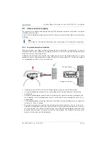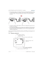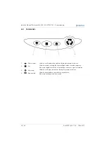
Installer Manual Performa 263-268 / LOGIX 740-760 - Installation
24 / 64
Ref. MKT-IM-011 / A - 15.06.2017
5.4.
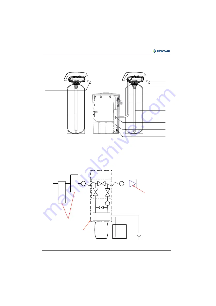
Block diagram and configuration example
Configuration example :
Performa 263
Block diagram
1002449
Main inlet
Pressure
regulat
o
r
Filter
cart
ridge
Gauge
By-pass
Mixer
User’s line
Valve
Turbine
Suggested options
Resin
tank
Drain
Brine line
Check valve to prevent water
hammer and eventual hot
water returns.
Gauge
Configuration example :
Performa 268
MS-R13460
Correct drain line flow control
must be fitted depending on
media type and vessel size.
MS-4566PO
AV140
MS-506PO
1002449
1009116
CC-H4400-36.5
CC-H1035-34.75
CC-H7025-24HF
MS-R13460
Can be integrated in
the valve


