background image

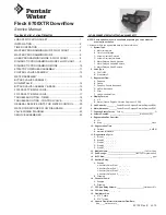
Fleck 6700XTR Downflow

Service Manual


42132 Rev E     JL10

TABLE OF CONTENTS

JOB SPECIFICATION SHEET ...............................................1
INSTALLATION ......................................................................2
TIMER OPERATION ..............................................................2
MASTER PROGRAMMING MODE FLOW CHART ...............4
MASTER PROGRAMMING MODE ........................................6
USER PROGRAMMING MODE & FLOW CHART .................8
DIAGNOSTIC PROGRAMMING MODE FLOW CHART ........9
DIAGNOSTIC PROGRAMMING MODE  ...............................10
6700XTR POWERHEAD ASSEMBLY ....................................11
CONTROL VALVE ASSEMBLY ..............................................12
METER ASSEMBLY ...............................................................13
BYPASS VALVE ASSEMBLY,  

NON-METALLIC .....................................................................14
BYPASS VALVE ASSEMBLY, BRASS ....................................15
2300 SAFETY BRINE VALVE.................................................16
2310 SAFETY BRINE VALVE.................................................17
TROUBLESHOOTING - TIMER .............................................18
TROUBLESHOOTING - CONTROL VALVE ...........................19
GENERAL SERVICE HINTS FOR METER CONTROL .........20
WATER CONDITIONER FLOW DIAGRAMS .........................21
VALVE WIRING DIAGRAM ....................................................22
SERVICE ASSEMBLIES ........................................................23

JOB SPECIFICATION SHEET

NOTE: Some options may not be available depending on valve model or 

other options chosen.

Circle and/or fill in the appropriate data for future reference.

1.  System Type:

A.  Meter Immediate
B.  Time Clock Delayed
C.  Volume Override Delayed
D.  Volume Override Immediate
E.  Meter Delayed Weekly Reserve
F.  Meter Delayed Variable Reserve
G.  Meter Delayed Fixed Reserve

2.  Valve Type:

A.  56XT/6700
B.  Proprietary C

3.  Regenerant Flow:

A.  Downflow
B.  Upflow
C.  Downflow Double Backwash
D.  Upflow Backwash
E.  Filter
F.  Upflow Variable Flow

4.  Display Format:

A.  U.S.
B.  Metric (French Degrees, German Degrees, or PPM)

5.  Unit Capacity: ���������

Grains/French Degrees/German Degrees/PPM

6.  Water Hardness: �������

Grains/French Degrees/German Degrees/PPM

7.  Capacity Safety Factor:  

Zero or______________________________%

8.  Volume Override:  ����������������������������

(Gallons or M

3

)

9.  Regeneration Day Override:


A.  Off
B.  Every ______________________________________________ Days

10.  Regeneration Time:

A.  Delayed __________________________________________ AM/PM
B.  Metered Immediate

11.  Regeneration Cycle:

A.  Step #1 _ _ : _ _ : _ _
B.  Step #2 _ _ : _ _ : _ _
C.  Step #3 _ _ : _ _ : _ _
D.  Step #4 _ _ : _ _ : _ _
E.  Step #5 _ _ : _ _ : _ _

12.  Media Volume: ����������������������������������

(CuFt or Liter) 

13.  Salt Dosage:  ���������������������������

(lbs/CuFt or grams/Liter)

14.  BLFC Size:

 _____________________________________________ gpm

15.  Auxiliary Relay:

A.  Enabled

a. Auxiliary Relay Start 1 _ _ : _ _ : _ _
b. Auxiliary Relay End 1 _ _ : _ _ : _ _
c. Auxiliary Relay Start 2 _ _ : _ _ : _ _
d. Auxiliary Relay End 2 _ _ : _ _ : _ _

B.  Disabled

16.  Chemical Pump:

A.  Enabled
B.  Disabled

17.  CPO Aux Relay Volume: �������������������������

(Gallons or M

3

)

18.  CPO Aux Relay:

 _ _ : _ _ : _ _

19.  Flow Meter Size:

A.  0.75" Paddle
B.  0.75" Turbine

20.  Generic Flow Meter for Maximum Flow Rate:  

Add_____Gallons every _ _

Summary of Contents for Fleck 6700XTR

Page 1: ...Downflow Double Backwash D Upflow Backwash E Filter F Upflow Variable Flow 4 Display Format A U S B Metric French Degrees German Degrees or PPM 5 Unit Capacity Grains French Degrees German Degrees PPM...

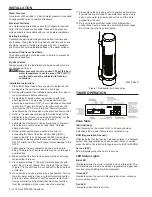
Page 2: ...connecting the Drain Line Flow Control fitting DLFC Leave at least 6 15 cm between the DLFC and solder joints when soldering pipes that are connected on the DLFC Failure to do this could cause interi...

Page 3: ...regeneration press the Extra Cycle button again to cancel If regeneration occurs for any reason prior to the delayed regeneration time the manual regeneration request shall be cleared Queued Regenera...

Page 4: ...set To Set Time Of Day Press and hold the Up and Down buttons for 2 seconds Press the Shift button to select the digit you want to modify Entering Master Programming Mode Press and hold the Shift and...

Page 5: ...MASTER PROGRAMMING MODE FLOW CHART continued Fleck 6700XTR Downflow JL10 5...

Page 6: ...p or Down buttons to adjust this value Press the Extra Cycle button 3 Regenerant Flow This program step selects how the regenerant flows through the tank must match cam The selections available will v...

Page 7: ...step sets the volume of the media in the resin tank Press the Shift button to select the digit you want to modify Press the Up or Down buttons to adjust this value Press the Extra Cycle button 13 Salt...

Page 8: ...e Up or Down buttons to adjust this value Press the Extra Cycle button 19 End of Master Programming Mode Press the Extra Cycle button to save all settings and exit Master Programming Mode MASTER PROGR...

Page 9: ...Mode 1 Press and release the D button 2 Press the Extra Cycle button once per display until all displays are viewed and the normal display screen appears 3 Press and release the D button during this m...

Page 10: ...This program step displays the peak flow rate 1 minute average since the last regeneration Press the Extra Cycle button 3 Totalizer This program step displays the total volume of treated water that pa...

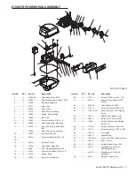
Page 11: ...nflow 1 4069 Cam Double Backwash D F 17 1 15151 Screw Flat Head St 6 20 x 3 4 18 2 10218 Switch Micro 19 1 10302 Insulator Limit Switch 20 2 17876 Screw Phil Pan 4 40 x 1 1 8 21 1 42194 Bracket Circui...

Page 12: ...088 Washer Flow 2 4 GPM 24 1 12094 Washer Flow 25 GPM 25 1 12550 Quad Ring 009 26 1 12626 Seat Brine Valve 27 1 12638 O ring 013 Injector 28 1 12977 O ring 015 29 1 13163 Body Injector 30 1 13165 Cap...

Page 13: ...4 1 13847 O ring 137 Std Meter 5 5 17798 Screw Slot Hex Wsh Hd 6 1 13821 Body Meter 5600 7 1 13509 Impeller Meter 8 4 12473 Screw Hex Wsh 10 24 x 5 8 9 4 13255 Clip Mounting 10 4 13314 Screw Slot Ind...

Page 14: ...Clip Mounting 3 2 13314 Screw Slot Ind Hex 8 18 x 60 4A 1 18706 Yoke 1 NPT Plastic 18706 02 Yoke 3 4 NPT Plastic 4B 1 41027 01 Yoke 3 4 NPT Cast Machd 41026 01 Yoke 1 NPT Cast Machd SS BYPASS VALVE AS...

Page 15: ...Top 5 1 11979 02 Lever Bypass Black 6 1 11986 Plate Bypass Bottom 7 8 15727 Screw Hex Wsh Hd 10 24 x 1 2 8 1 13604 03 Label Bypass Standard Mount 13604 04 Label Bypass Reverse Mount Blue 9 1 40974 Wa...

Page 16: ...Fill 4 1 10328 Fitting Elbow 90 Deg 1 4 NPT x 3 8 T 5 2 10332 Fitting Insert 3 8 6 2 10330 Fitting Sleeve 3 8 Celcon 7 2 10329 Fitting Tube 3 8 Nut Brass 8 1 10186 Nut Hex 10 32 Nylon 9 1 60002 Air Ch...

Page 17: ...on Black 5 1 19652 01 Poppet Assy SBV w o O ring 6 1 19649 Flow Dispenser 7 1 11183 O ring 017 8 1 19647 Elbow Safety Brine Valve 9 2 19625 Nut Assy 3 8 Plastic 10 1 18312 Retainer Drain 11 1 60014 Sa...

Page 18: ...e has occurred Either wait 5 minutes for blinking to stop or press any key on the keypad Unit not responding after going into regeneration Verify the unit is configured correctly ex wiring valve type...

Page 19: ...em Assure that well system has proper air eliminator control Check for dry well condition Improperly sized drain line flow control Check for proper drain rate Iron in conditioned water Fouled mineral...

Page 20: ...echnical support 2 Regen Failure The system has not regenerated for more than 99 days or 7 days if the Control Type has been set to Day of Week Perform a Manual Regeneration to reset the error code If...

Page 21: ...WATER CONDITIONER FLOW DIAGRAMS Service Position Backwash Position Brine Slow Rinse Position Rapid Rinse Brine Tank Fill Position Fleck 6700XTR Downflow JL10 21...

Page 22: ...VALVE WIRING DIAGRAM 22 JL10 Fleck 6700XTR Downflow...

Page 23: ...ine Valve 13302 O ring 014 16098 Washer Nylon Brine 13172 Brine Valve Stem 12626 Seat Brine Valve Floats 60028 XX 2300 Blue White Float 60068 XX 2310 Blue White Float Injector 60084 XX Injector Module...

Page 24: ...2010 Pentair Residential Filtration LLC 42132 Rev E JL10...

Reviews: