PRODUCT INSTALLATION INSTRUCTIONS
GOYEN IS/ISP SERIES CONTROLLER
DEINE-012
PAGE 2 of 24
©COPYRIGHT Goyen Controls Co. Pty. Ltd.
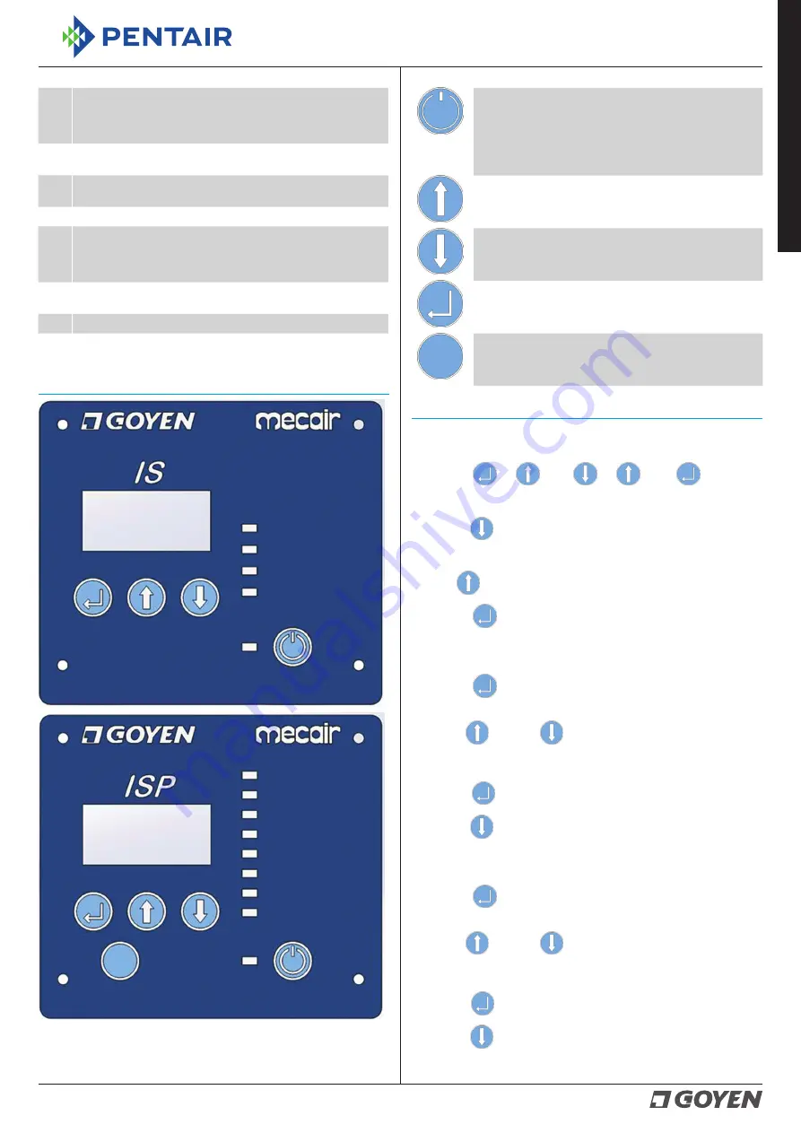
Power/Reset Button: This is used to turn the controller
ON and OFF and to conduct a Soft Reset. Once powered
ON using this button, the controller will relearn the
cleaning system. This button can be used to turn the
controller ON; however, the main power switch on
the base board must be in the ON position.
Press to scroll up through the menu.
Press to scroll down through the menu.
Press to enter settings.
Press to change between Demand or Continuous modes
(ISP only)
.
PROGRAMMING INSTRUCTIONS
To enter Programming Mode:
Press Select
, Up
, Down
, Up
, Select
The 'dP Low' LED should now be lit.
Press Down
to scroll down the list.
The LED indicates the function to be programmed.
Press Up
to scroll up the list.
Press Select
to change the settings for that function.
dP Low *
Press Select
when the ‘dP Low’ LED is lit.
This LED should start to flash indicating it is in programming mode.
Use the Up
and Down
buttons to select a low dP limit. When
in demand mode, the cleaning cycle will stop at this setting.
(Min. 00.0–Max. 03.8)
Press Select
to confirm the setting. The ‘dP Low’ LED should now be lit.
Press Down
to scroll down the list.
dP High *
Press Select
when the ‘dP High’ LED is lit.
This LED should start to flash indicating it is in programming mode.
Use the Up
and Down
buttons to select a high dP limit. When
in demand mode, the cleaning cycle will start at this setting.
(Min. 02.2–Max. 18.0)
Press Select
to confirm the setting. The ‘dP High’ LED should now be lit.
Press Down
to scroll down the list.
9
Fan Stop Input (Voltage Free): This input is used to stop the
controller remotely. It may be connected to the blower fan control
so the cleaning cycle automatically pauses in the event the fan
stops. Max. cable size 14–26 AWG.
10
Input Buttons: These buttons are used to control the menu and
program the controller.
11
Mode Switch: Use to change the controller between Continuous
Mode and dP Mode. (ISP only)
12
7-Segment LED: Display the menu and controller operation.
13
Interface Screen Socket (Optional): Ribbon cable socket for
the optional interface screen. Carefully insert the ribbon cable
securely into the socket and test the interface screen to confirm
it is functioning correctly.
14
Menu Interface LEDs: These show the status of the controller and
are used to indicate the setting during programing mode.
15
Power LED: When lit, it indicates the controller is powered ON.
16
dP Sensor: Connect the clean and dirty air lines to the sensor as
shown. (ISP only)
INTERFACE MODULE FUNCTIONS
On Time
Off Time
# Blowdown
Run
dP Low
dP High
dP Units
High dP Alarm
On Time
Off Time
# Blowdown
Run
Dem./Cont.
The Interface module comes standard with the enclosure and can be
ordered separately with the base board.
* ISP only
ENGLISH


