background image

Installation, Operation, Repair And Parts Manual

Rev. B

Description

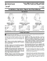
Series 5300C-X, 5321C, 5322C and 5324C

Small Twin

®

Piston and Plunger Pumps

Form L-0200P

The following special attention notices are used to notify
and advise the user of this product of procedures that
may be dangerous to the user or result in damage to the
product.

NOTE: Notes are used to notify of installation, oper-
ation, or maintenance information that is important
but not safety related.

CAUTION: Caution is used to indicate the presence
of a hazard, which will or can cause minor injury or
property damage if the notice is ignored.

WARNING: Warning denotes that a potential hazard
exists and indicates procedures that must be fol-
lowed exactly to either eliminate or reduce the haz-
ard, and to avoid serious personal injury, or prevent
future safety problems with the product.

DANGER: Danger is used to indicate the presence
of a hazard that will result in severe personal injury,
death, or property damage if the notice is ignored.

Safety Information

SERIES 5321C & 5322C

Cast Iron Small Twin

Plunger Pump

Max. Flow Rate:

........................2.2 gpm

Max. Pressure:

........................1000 psi

Max. Speed:

............................1725 rpm

Ports:

................................1/2" NPT inlet

1/2" NPT outlet

Max. Operating Temp.

..............180o F

SERIES 5300C-X

Cast Iron Small Twin

Piston Pump

SERIES 5324C

Cast Iron Small Twin

Piston Pump

Max. Flow Rate:

........................2.9 gpm

Max. Pressure:

..........................800 psi

Max. Speed:

............................1725 rpm

Ports:

................................1/2" NPT inlet

1/2" NPT outlet

Max. Operating Temp.

..............140o F

Max. Flow Rate:

..................1.5, 2.0, 2.5

and 3.0 gpm

Max. Pressure:

..........................500 psi

Max. Speed:

............................1725 rpm

Ports:

................................1/2" NPT inlet

1/2" NPT outlet

Max. Operating Temp.

..............140o F

DANGER: DO NOT pump flammable or explosive
fluids such as gasoline, fuel oil, kerosene, etc. DO
NOT use in explosive atmospheres. The pump
should be used only with liquids compatible with the
pump component materials. Failure to follow this
warning can result in personal injury and/or proper-
ty damage and will void the product warranty.

A pressure relief device, such as an unloader, relief
valve or balancing regulator must be installed on the
outlet side of the pump. Failure to do so could
result in personal injury and/or void the warranty.

Be sure all exposed moving parts such as shafts,
couplers and adapters are properly shielded or
guarded and that all coupling devices are securely
attached before applying power.

Hollow shaft pumps mounted directly onto power
shaft must be prevented from rotating with the
power shaft by means of a device such as a torque
arm. Pump must float freely on the power shaft and
must not be tied rigidly to equipment on which it is
mounted.

HYPRO

®

®

California Proposition 65 Warning 

-- This product and related accessories contain chemicals known to the

State of California to cause cancer, birth defects or other reproductive harm.

Summary of Contents for HYPRO Small Twin 5300C-X Series

Page 1: ...Cast Iron Small Twin Piston Pump Max Flow Rate 2 9 gpm Max Pressure 800 psi Max Speed 1725 rpm Ports 1 2 NPT inlet 1 2 NPT outlet Max Operating Temp 140o F Max Flow Rate 1 5 2 0 2 5 and 3 0 gpm Max Pr...

Page 2: ...earance between cou pling ends and center disc Tighten screws in both cou pling ends For electric motor drive use couplings rated at least twice the horsepower required to operate pump For gas engine...

Page 3: ...is over 5 feet long use the next larger size hose Keep the suction hose as short as possible and restrictions such as elbows check valves etc at a minimum Discharge Hose High pressure pumps require th...

Page 4: ...more than 30 seconds 2 Temperature rise Overheating is harmful to bear ings and piston cups NOTE Models 53702 and 53703 Inlet Requirements Pressure feed 20 to 100 psi Care of Pump Your pump will last...

Page 5: ...Bearing area closest to the Cam Bearing Check for cracks in the Pump Body particularly at the discharge port and along the casting seam See Figure 7 2 Inspect for excessive wear on the Cylinder Heads...

Page 6: ...e Cage and pull up with a twisting motion To remove Valve Seat Hook Valve Seat Extractor under Seat and work out with an up and down motion 5 Rotate the Pump Shaft so the Cam Bearing is in the upstrok...

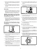
Page 7: ...spring or ten sion loaded fasteners or devices 1 Place the pump on a flat surface with the shaft side facing up then remove the retaining ring from the bearing bore 2 Using a metal pipe 3 in diameter...

Page 8: ...the Seal then place the Seal Retainer over the Support Ring side of the Support Ring Seal combination 2 Press the above items in with your fingers until the Support Ring Seal combination bottoms out...

Page 9: ...e the arbor press ram to press the Crankshaft Assembly into the bearing bore of the pump body until it bottoms out 8 Place the front Main Bearing on the Crankshaft until it touches the pump body 9 Pla...

Page 10: ...der 12 Place the Cup Spreader end opposite O ring in the Cup inside the piston bore 13 Place the Washer on the Piston Cap Screw insert it through the Piston Assembly then tighten it to 130 in lbs of t...

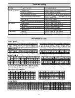
Page 11: ...6 1 0 6 7 6 0 0 7 6 6 8 8 8 5 2 7 1 2 8 1 2 3 1 8 9 5 4 0 8 2 9 6 0 8 5 1 8 9 7 9 5 0 1 Series 53702 Series 53703 Series 5300C X Series 5321C and 5322C NOTE Above performance figures based on constant...

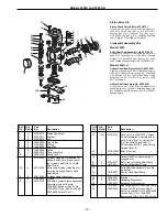
Page 12: ...PART NUM BER DESCRIPTION and COM PLETE MODEL NUMBER Reference numbers are used ONLY to identify parts in the drawing and are NOT to be used as order numbers 2 2 2220 0012 Piston Cap Screw 3 2 2270 00...

Page 13: ...sing 32 1 1510 0041 Mounting Base for Solid Shaft Models 33 1 3420 0030 Torque Arm Kit for Hollow Shaft Models Consists of No 2820 0035 Torque Arm No 1450 0003 Bumper and two No 2210 0064 Bolts 34 2 2...

Page 14: ...rts Kit No 3430 0292 Consists of one No 3430 0291 Plunger Stack Parts Kit and two No 3500 0036 Plungers Ref Qty Part No Req d No Description Ref Qty Part No Req d No Description 18 1 Set 3430 0197 Set...

Page 15: ...1A 4 2210 0064 Extra Long Cylinder Head Bolt for securing mounting base to Solid Shaft Pump 12 2 0201 5300C Cylinder Head Cast Iron 13 2 1720 0038 O Ring 14 1 3430 0210 Ni Resist Cylinder Sleeve Assem...

Page 16: ...lve prevents back flow of liquid from the pump into the injector This allows application of soap detergent and other solutions through the injector then by closing the injector supply followed by a cl...

Page 17: ...ENANCE If opening around needle valve stem becomes clogged clean the valve stem and passage way with warm soapy water Rotate the control knob assembly counter clockwise which includes the control knob...

Page 18: ...18 NOTES...

Page 19: ...19 NOTES...

Page 20: ...emicals must be labeled tagged before being shipped to Hypro for service or warranty consideration Hypro reserves the right to request a Material Safety Data Sheet from the returnee for any pump produ...

Reviews: