6
SandShark
™
Installation and User’s Guide
Optional Installation,
cont’d.
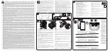
Adjust Flow
1. With the main drain closed, and one end of the hose attached to the vacuum
regulator installed in the skimmer, insert the flow gauge into the other end of
the hose (the end with the “leader” hose attached).
2. Keep the hose and flow gauge underwater.
3. Turn on the pump. With the pump running, adjust the vacuum regulator
(in your skimmer) until the indicator on the flow gauge is between minimum and
maximum flow (Figure 21).
4. Use the vacuum regulator in conjunction with your pool cleaner system at all
times. The vacuum regulator has an adjustment knob, (see Figure 22). If
suction is too high, the knob is turned counterclockwise to decrease the
suction. If the suction is too low, the knob is turned clockwise to increase the
suction.
NOTE: The flow gauge is calibrated for use with the “Y” shaped vacuum
regulator valve. The flow gauge will not indicate the correct flow for the
cleaner if you are not using the “Y” shaped vacuum regulator valve.
5. Remove the flow gauge from the end of the hose (the end with the “leader”
hose attached) and attach the “leader” hose to the cleaner’s swivel.
Connect the Hose to the Cleaner
1. Connect the leader hose to the cleaner (correct end of hose is marked
with a red label), (see Figure 23).
2. Fill the cleaner with water and let it sink to the bottom, (see Figure 24).
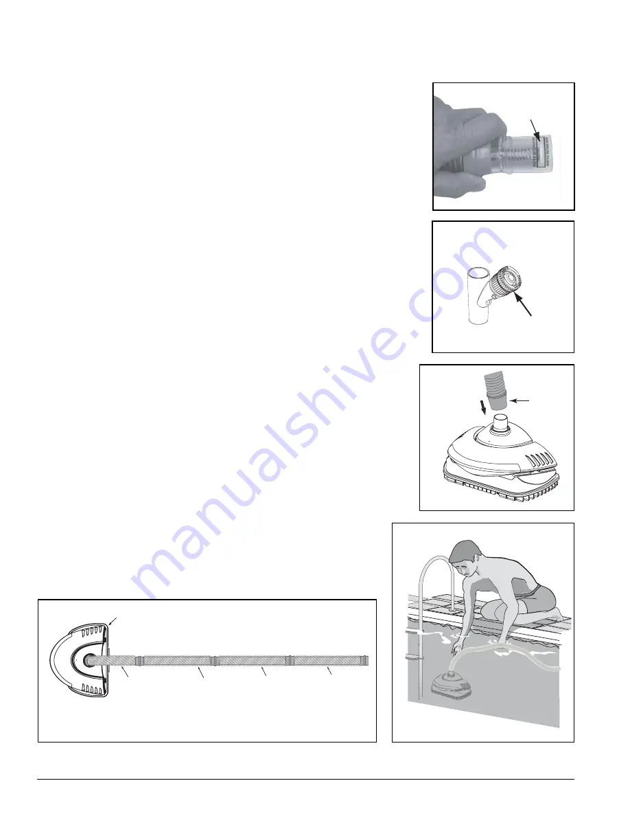
3. Verify hose connections as shown in Figure 25.
Disc Indicator
Figure 21.
Flow Indicated on Flow Gauge.
Le
ad
er H
o
se
m
a
rke
d
"
Conn
e
ct
to
Cl
e
an
er"
Figure 23.
Figure 24.
S
and
S
ha
rk
cl
e
an
er
Th
e
ho
se
m
u
s
t
e
qual th
e
long
es
t d
is
tanc
e
f
r
o
m
th
e
s
uct
i
on conn
e
ct
i
on
to th
e
fu
r
th
es
t po
i
nt
i
n th
e
pool, plu
s
on
e
ho
se
se
ct
i
on l
e
ngth,
plu
s
th
e
12
i
n. l
e
ad
er
ho
se
.
S
ho
r
t, 12
i
n.
Le
ad
er
ho
se
must be
installed
Se
cond ho
se
Se
ct
i
on
Th
ir
d ho
se
Se
ct
i
on
Fou
r
th ho
se
Se
ct
i
on
Figure 25.
Figure 22.
Vacuum
Regulator
Adjustment
Knob
Summary of Contents for Kreepy Krauly SandShark 7900
Page 22: ...16 SandShark Installation and User s Guide NOTES...
Page 23: ...SandShark...
Page 24: ...P N 39503 6300 Rev A 10 27 08...