background image

23833A148  12/05/12

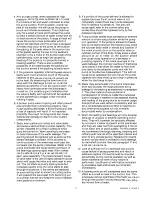
has been added approximately .030 shim, and 

tighten the four cap screws to recommended torque.

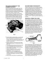
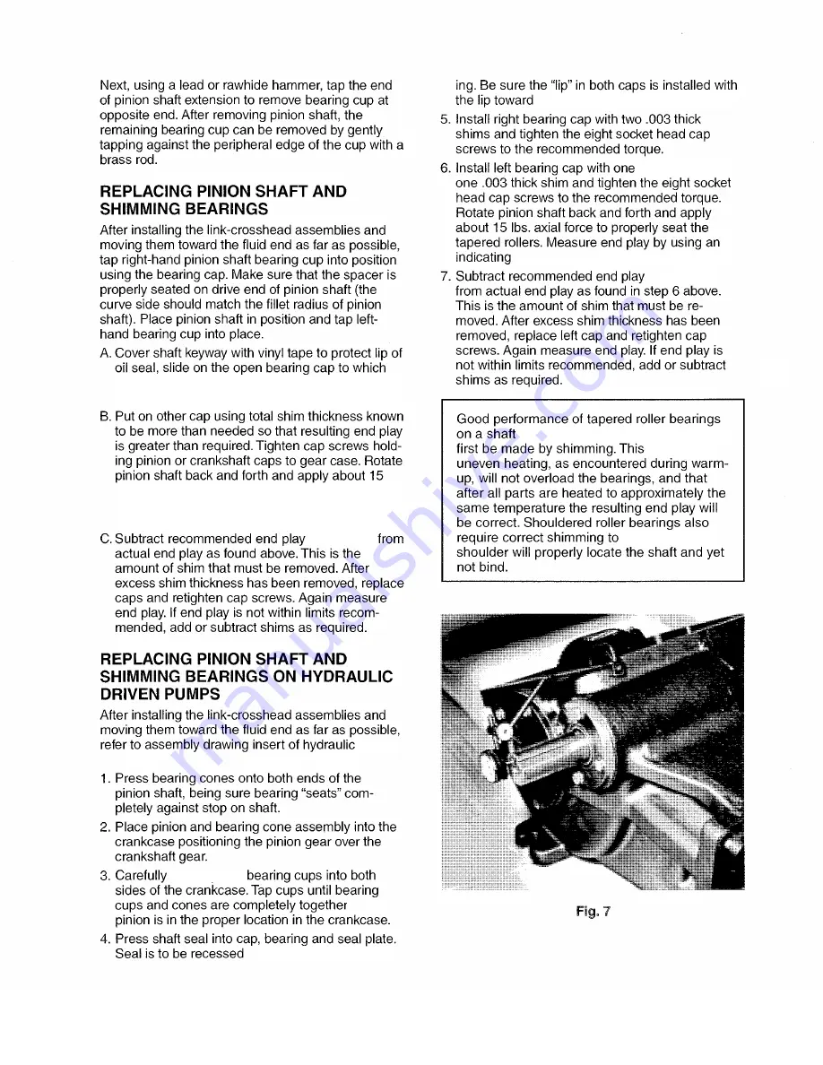
axial force to properly seat tapered rollers. Measure 

end play by using an indicating gauge in a manner 

shown in Fig.7.

lbs.

(.005 – .009)

driven pumps.

hand-press

and

"

8

1

the center of the pump as shown.

.015 thick and

gauge in a manner as shown in Fig. 7.

(.005 

 .009)

requires that correct shaft end play

ensures that

ensure that the

as indicated in draw-

7

Summary of Contents for MYERS DP Series

Page 1: ...lease make sure you provide this manual to the owner of the equip ment or to the responsible party who maintains the system DP SERIES INDUSTRIAL PUMP INSTALLATION AND SERVICE MANUAL Part 23833A148 201...

Page 2: ...12 DP120 12AB 120 454 1 200 82 7 1800 456 2 5 8 66 7 99 73 9 A Ductile Iron Aluminum Bronze A 24960F001 24960F011 DP90 18 DP90 18AB 88 333 1 700 117 2 1800 456 2 1 4 57 2 103 76 8 A Ductile Iron Alum...

Page 3: ...e that an operating pressure gauge is located in discharge line Use heavy duty liquid filled pulsation free pressure gauge 6 Make sure all valves including spray gun or nozzles are open in discharge l...

Page 4: ...wer train life may be doubled between overhauls The chart below gives volume of MoS2 concentrate required DP Series 61 2 Qts 10 Fl Oz 20 Fl Oz PINION RPM RANGE GEAR CASE CAPACITY 1600 1800 6 quarts 10...

Page 5: ...80 slide AL BR seal back ring 61 into bore until it bottoms out and seats in place 3a For models DP70 DP55 DP40 and DP28 place spacers and braided packing rings refer to Fig 1 into the seal cartridge...

Page 6: ...or nibbling Lubricate O rings and replace valve cap Torque valve cap until it stops CAUTION Do not use a hand or arbor press to by and unscrewing and pushing ceramic plunger toward and replace if Figu...

Page 7: ...properly seat tapered rollers Measure end play by using an indicating gauge in a manner shown in Fig 7 lbs 005 009 driven pumps hand press and 8 1 the center of the pump as shown 015 thick and gauge i...

Page 8: ...s at 13 foot pounds rotate the crankshaft and retorque the cap screws Do this three times to properly seat the tapered roller bearings 3 1240 3 1245 Contact Engineering Department refit connecting lin...

Page 9: ...23833A148 12 05 12 9...

Page 10: ...23833A148 12 05 12 in some cases it will 10...

Page 11: ...23833A148 12 05 12 is lubrication instructions disrupting are drawn can be detected only by visual examination of bypassed and recirculated back will not operate satisfactorily or quietly 11...

Page 12: ...23833A148 12 05 12 This will become evident only after the rod and check for Drain bypass line by disconnecting or if there is a drain point remove plug ensure valves do not frost to 12...

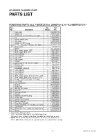
Page 13: ...g O ring O ring New part for DP Power End L H Left Hand Drive and R H Right Hand Drive Picture on cover of these instructions illustrates right hand drive pump NOTE When purchasing the crankshaft or p...

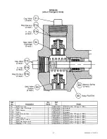
Page 14: ...rge valve spring cap thrd lock packing packing packing coated seal back seal O ring seal cartridge 2 Ring backup seal cartridge 2 plunger spring cylinder pipe pipe after August 1996 models models exce...

Page 15: ...d end models models models after 13 August 1996 after 13 August 1996 after 13 August 1996 after 13 August 1996 after 13 August 1996 after 13 August 1996 after 13 August 1996 O ring O ring suction valv...

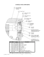
Page 16: ...2 05674A020 Cone bearing 6 2 05675A019 Cup bearing 7 2 04741B010 Cap bearing seal 8 2 05710A046 Seal oil 9 2 17272A013 Protector plastic 10 16 06106A048 Screw cap socket head Grade 8 5 16 24UNF x 1 lo...

Page 17: ...23833A148 12 05 12 17...

Page 18: ...THIS PAGE INTENTIONALLY LEFT BLANK...

Page 19: ...THIS PAGE INTENTIONALLY LEFT BLANK...

Page 20: ...s or malfunctions resulting from failure to properly install operate or maintain the unit in accordance with the printed instructions provided b to failures resulting from abuse accident or negligence...

Reviews: