background image

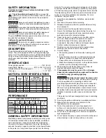
SAFETY INFORMATION

Carefully read and follow all safety instructions in this 

manual or on pump.

This is the safety alert symbol. When you see this 

symbol on your pump or in this manual, look for one of 

the following signal words and be alert to the potential for  

personal injury!

warns about hazards that will cause serious 

personal injury, death or major property damage if ignored.

warns about hazards that can cause serious 

personal injury, death or major property damage if ignored.

warns about hazards that will or can cause 

minor personal injury or property damage if ignored.

The word NOTICE indicates special instructions which are 

important but not related to hazards.

California Proposition 65 Warning

This product and related accessories contain 

chemicals known to the State of California to cause cancer, 

birth defects or other reproductive harm.

DESCRIPTION

These Submersible Sump Pumps are designed for home 

sumps. The unit is equipped with a 3-prong grounding-type 

power cord. The shaded-pole motor is oil filled and sealed for 

cooler running. Upper sleeve/lower ballbearing on the motor 

shaft never need lubrication. Automatic reset thermal  

protection.

SPECIFICATIONS

Power supply required.........................................115V, 60 HZ.

Liquid Temp. Range .......................... 32°F to 130°F (0°-54°C)

Individual Branch Circuit Required: ............................15 Amps

Discharge ............................................................... 1-1/2” NPT

PERFORMANCE

GENERAl SAFETY INFORMATION

Electrically powered sump pumps normally give many years 

of trouble-free service when correctly installed, maintained, 

and used. However, unusual circumstances (interruption 

of power to the pump, dirt/debris in the sump, flooding that 

exceeds the pump’s capacity, electrical or mechanical failure 

in the pump, etc.) may prevent your pump from functioning 

normally. To prevent possible water damage due to flooding, 

consult your dealer about installing a secondary sump pump, 

a DC backup sump pump, and/or a high water alarm. See the 

“Troubleshooting Chart” in this manual for information about 

common sump pump problems and remedies. For more 

information, see your dealer.
1.  Know the pump application, limitations, and potential 

hazards.

2.  Disconnect the power before servicing.

3.  Release all pressure within the system before servicing 

any component.

4.  Drain all water from the system before servicing.

5.  Secure the discharge line before starting the pump. An 

unsecured discharge line will whip, possibly causing 

personal injury and/or property damage.

6.  Check the hoses for a weak or worn condition before 

each use. Make certain all connections are secure.

7.  Periodically inspect the sump, pump and system 

components. Keep free of debris and foreign objects. 

Perform routine maintenance as required. 

8.  Provide a means of pressure relief for pumps whose 

discharge line can be shut-off or obstructed.

9.  Personal Safety:

a.  Wear safety glasses at all times when working with 

pumps.

b.  Keep the work area clean, uncluttered and properly 

lighted – replace all unused tools and equipment.

c.  Keep visitors at a safe distance from work area.

d.  Make the workshop child-proof – with padlocks, master 

switches, and by removing starter keys.

10. When wiring an electrically driven pump, follow all 

electrical and safety codes that apply.

11. This equipment is only for use on 115 volt (single 

phase) and is equipped with an approved 3-conductor 

cord and 3-prong, grounding-type plug.


Electrical shock hazard. Can burn or kill. 

To reduce risk of electric shock, pull plug before servicing. 

Pump is supplied with a grounding conductor and 

grounding-type attachment plug. Be sure it is connected 

only to a properly grounded grounding-type receptacle.


Where a 2-prong wall receptacle is encountered, it must 

be replaced with a properly grounded 3-prong receptacle 

installed in accordance with codes and ordinances that 

apply.


This pump has not been investigated for use in swimming 

pool areas.

12. All wiring should be performed by a qualified electrician.

13. Make certain the power source conforms to the 

requirements of your equipment.

14. Protect the electrical cord from sharp objects, hot 

surfaces, oil, and chemicals. Avoid kinking the cord. 

Replace or repair damaged or worn cords immediately.

15. Do not touch an operating motor. Motors can operate at 

high temperatures.

16. Do not handle the pump or pump motor with wet hands or 

when standing on wet or damp surface, or in water.

2

GPM (LPM) AT TOTAL FEET (m)

                   5        10       15        20        25 

 Model    (1.5m)  (3m)   (4.6m)  (6.1m)  (7.6m)

        CAPACITY GAllONS(l)/MINUTE
 MCI033
     48        40       29        15        -      24 Ft.

                (182)     (151)    (110)    (57)              (7.3m)

 MCI050     62        53        46        38      29    32 Ft.

                (235)     (201)    (174)    (144)  (110)  (9.8m)

No flow  

at height 

shown 

below


Full  

Individual

  Model 

Motor 

load 

Branch Circuit 

Cord

   Number 

HP 

Amps 

Required (Amps)  length

 MCI033 

1/3 

9.8 

15 

10’

 MCI033-20 

1/3 

9.8 

15 

20’

 MCI033-30 

1/3 

9.8 

15 

30’

 MCI050 

1/2 

12.0 

15 

10’

 MCI050-20 

1/2 

12.0 

15 

20’

 MCI050-30 

1/2 

12.0 

15 

30’

MOTOR & CORD SPECIFICATIONS

Summary of Contents for MYERS MCI033

Page 1: ...e 1 888 987 8677 Français Pages 7 11 Instalación Operación Piezas Para mayor información sobre el funcionamiento instalación o mantenimiento de la bomba Llame al 1 888 987 8677 Español Paginas 12 16 OWNER S MANUAL Submersible Sump Effluent Pump NOTICE D UTILISATION Pompe de puisard d effluents submersible MANUAL DEL USUARIO Bomba de sumidero efluente sumergible 2014 Pentair Inc All Rights Reserved...

Page 2: ...tarting the pump An unsecured discharge line will whip possibly causing personal injury and or property damage 6 Check the hoses for a weak or worn condition before each use Make certain all connections are secure 7 Periodically inspect the sump pump and system components Keep free of debris and foreign objects Perform routine maintenance as required 8 Provide a means of pressure relief for pumps ...

Page 3: ...er trapped in the discharge to freeze which could result in damage to the pump 10 After the piping and check valve have been installed the unit is ready for operation 11 Check the operation by filling the sump with water and observing pump operation through one complete cycle Risk of Flooding Failure to make this operational check may lead to improper operation premature failure and flooding Opera...

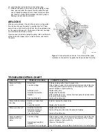
Page 4: ...nded minimum check the size delivers little or no of the wiring from the main switch on the property If OK contact water power company or hydro authority Something is caught in Clean out the impeller impeller Anti airlock hole is plugged Turn off the pump clean out the anti airlock hole and restart pump 10 Insert the float rod in the hole in the tether strap 11 Reinstall the pump in the sump check...

Page 5: ... Nos 2A 2B 2C 1 U9 471REP U9 471REP 3 Power Cord 10 1 PW117 237 TSU PW117 237 TSU Power Cord 20 1 PW17 122 PW17 122 Power Cord 30 1 PW17 293 PW17 293 4 Motor 1 5 Shaft Seal 1 21607A001 21607A001 6 Impeller 1 PS5 26P PS5 29P 7 Lower Volute 1 PS1 34P PS1 34P 8 Suction Plate 1 U43 142SS U43 142SS 9 Switch Float Kit Includes Float Switch Rod Rod Stops and 1 PS28 37REP PS28 37REP Tether Strap ...

Page 6: ...GOING LIMITED WARRANTIES SHALL NOT EXTEND BEYOND THE DURATION PROVIDED HEREIN Some states do not allow the exclusion or limitation of incidental or consequential damages or limitations on the duration of an implied warranty so the above limitations or exclusions may not apply to You This warranty gives You specific legal rights and You may also have other rights which vary from state to state Duri...

Page 7: ...biliser la conduite de refoulement avant de démarrer la pompe Une conduite de refoulement non immobilisée risque de fouetter et de causer possiblement des blessures corporelles et ou des dommages matériels 6 Avant chaque utilisation s assurer que tous les tuyaux souples ne présentent aucun signe de faiblesse ou d usure et que tous les raccords sont bien serrés 7 Inspecter périodiquement le puisard...

Page 8: ...tures extérieures inférieures à zéro l installer de façon à ce qu elle se vidange par gravité Sinon l eau restant dans la conduite risque de geler et d endommager la pompe 10 Après l installation de toutes les conduites et du clapet antiretour la pompe est prête à fonctionner 11 Vérifier le fonctionnement en remplissant le puisard avec de l eau et en observant le fonctionnement de la pompe sur un ...

Page 9: ...libre du câblage côté disjoncteur principal de la propriété Si tout est correct s adresser à la compagnie d électricité Moteur défectueux Remplacer la pompe Interrupteur à flotteur défectueux Remplacer l interrupteur à flotteur L impulseur Si l impulseur ne tourne pas débrancher la pompe déposer son corps inférieur et trouver la source de grippage Au besoin remplacer l impulseur Flotteur obstrué E...

Page 10: ...P réf n 2A 2B 2C 3 Cordon électrique 10 1 PW117 237 TSU PW117 237 TSU Cordon électrique 20 1 PW17 122 PW17 122 Cordon électrique 30 1 PW17 293 PW17 293 4 Moteur 1 5 Joint d arbre 1 21607A001 21607A001 6 Impulseur 1 PS5 26P PS5 29P 7 Volute inférieure 1 PS1 34P PS1 34P 8 Plaque d aspiration 1 U43 142SS U43 142SS 9 Ensemble d interrupteur à flotteur flotteur tige d interrupteur 1 PS28 37REP PS28 37R...

Page 11: ...eul recours de l Acheteur et la seule responsabilité de F E MYERS consistent à réparer ou à remplacer au choix de F E MYERS les produits qui se révéleraient défectueux L Acheteur s engage à payer tous les frais de main d œuvre et d expédition du produit couvert par sa garantie et de s adresser au concessionnaire installateur ayant procédé à l installation dès qu un problème est découvert pour obte...

Page 12: ... del sistema antes de efectuar reparaciones 5 Asegure bien la tubería de descarga antes de poner en marcha la bomba Una tubería de descarga que no esté bien segura puede mov erse y causar lesiones personales y o daños materiales 6 Antes de cada uso verifique si las mangueras están débiles o gasta das asegurándose de que todas las conexiones estén firmes 7 Inspeccione periódicamente el sumidero la ...

Page 13: ... esta precaución existe el riesgo de que el agua que quede atrapada en la descarga se congele y dañe la bomba 10 Después de que se haya instalado la tubería y la válvula de retención la bomba estará lista para su funcionamiento 11 Verifique el funcionamiento de la bomba llenando el sumidero con agua y haciendo funcionar la bomba a través de un ciclo completo Riesgo de inundación El incumplimien to...

Page 14: ...o comuníquese con la empresa de energía o de suministro de corriente eléctrica Motor defectuoso Cambie la bomba Conmutador de flotación Cambie el conmutador de flotador defectuoso Impulsor Si el impulsor no gira saque el cuerpo inferior de la bomba y ubique la fuente de atascamiento Flotador obstruido Elimine la obstrucción La bomba arranca y se Retroflujo de agua desde Instale o cambie la válvula...

Page 15: ...es Nos 2A 2B 2C 3 Cordón eléctrico 10 1 PW117 237 TSU PW117 237 TSU Cordón eléctrico 20 1 PW17 122 PW17 122 Cordón eléctrico 30 1 PW17 293 PW17 293 4 Motor 1 5 Sello del eje 1 21607A001 21607A001 6 Impulsor 1 PS5 26P PS5 29P 7 Voluta inferior 1 PS1 34P PS1 34P 8 Tubería de placa 1 U43 142SS U43 142SS 9 Juego de Interruptor y Flotador incluye el flotador la barra del 1 PS28 37REP PS28 37REP interru...

Page 16: ...XTENDERÁN MÁS ALLÁ DE LA DURACIÓN INDICADA EN LA PRESENTE Ciertos estados no permiten la exclusión o limitación de daños incidentales o consecuentes o la aplicación de limitaciones en la duración de garantías implícitas de modo que es posible que las limitaciones o exclusiones que preceden no correspondan en su caso Esta garantía LE otorga derechos y obligaciones legales específicos sin embargo es...

Reviews: