
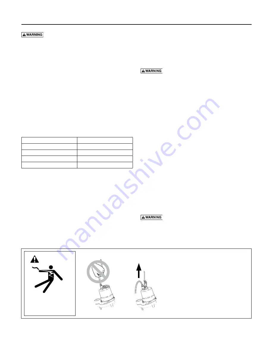
Risk of electric shock. Can shock, burn
or kill. Do not lift pump by the power cord. See Cord
Lift Warning.
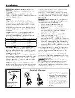
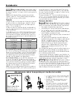
NOTICE Install the pump on a hard, level surface
(cement, asphalt, etc.). Never place the pump directly on
earth, clay or gravel surfaces.
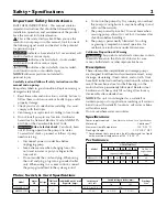
Piping
Piping must not be smaller than pump discharge.
When installed in a sewage system, the pipe must be
capable of handling semi-solids of at least 2” (51mm)
in diameter.
When installed in an effluent system, the pipe must be
capable of handling semi-solids of at least 3/4” (19mm)
in diameter.
The rate of flow in the discharge pipe must keep any
solids present in suspension in the fluid. To meet
minimum flow requirements (2 feet per second in the
discharge line), size the pipe as follows:
A Pipe Size Of:
Will Handle a Flow Rate Of:
1-1/2” (38mm)
12 GPM
2” (51mm)
21 GPM
2-1/2” (64mm)
30 GPM
3” (76mm)
48 GPM
In a sewage system use a 2” (51mm) check valve in
pump discharge to prevent backflow of liquid into sump
basin. The check valve should be a free flow valve that
will easily pass solids. Be sure check valve installation
complies with local codes.
In an effluent system use a 1-1/2” (38mm) check valve in
pump discharge to prevent backflow of liquid into sump
basin. The check valve should be a free flow valve that
will easily pass solids. Be sure check valve installation
complies with local codes.
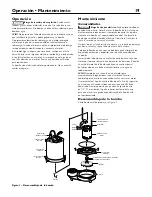
NOTICE For best performance of check valve when
handling solids, do not install it with the discharge more
than 45° above the horizontal. Do not install the check
valve in a vertical position as solids may settle in the
valve and prevent it from opening on startup.
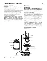
Drill a 3/16” (5mm) hole in the discharge pipe about
1–2” (25-51mm) above the pump discharge connection
(but below check valve) to prevent airlocking the pump.
Electrical
Risk of electric shock. Can shock, burn or
kill. When installing, operating, or servicing this pump,
follow the safety instructions listed below.
1. DO NOT splice the electrical power cord.
2. DO NOT allow the electrical cord plug to
be submerged.
3. DO NOT use extension cords. They are a fire hazard
and can reduce voltage sufficiently to prevent
pumping and/or damage motor.
4. DO NOT handle or service the pump while it is
connected to the power supply.
5. DO NOT remove the grounding prong from the
plug or modify the plug. To protect against electrical
shock, the power cord is a three-wire conductor and
includes a 3-prong grounded plug. Plug the pump
into a 3-wire, grounded, grounding-type receptacle.
Connect the pump according to the NEC or CEC and
local codes.
For automatic operation, plug or wire the pump into an
automatic float switch or duplex controller. The pump
will run continuously when plugged directly into an
electrical outlet.
Connect or wire pump to its own individual branch
circuit with no other outlets or equipment in the circuit.
Size fuses or circuit breakers according to Motor, Switch
and Cord Specifications.
Risk of electric shock. Can shock, burn or
kill. Be sure that power supply information (Voltage/
Hertz/Phase) on pump motor nameplate matches
incoming power supply exactly. Install pump according
to all electrical codes that apply.
Installation
4
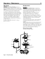
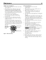
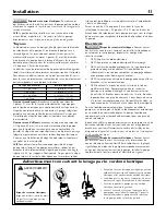
Cord Lift Warning
1. Attempting to lift or support pump by power
cord can damage cord and cord connections.
2. Cord may pull apart, exposing bare wires
with possibility of fire or electrical shock.
3. Lifting or supporting pump by power cord
will void warranty.
4. Use lifting ring or handle on top of pump
for all lifting/lowering of pump. Disconnect
power to pump before doing any work
on pump or attempting to remove pump
from sump.
Risk of electrical shock.
Can burn or kill.
Do not lift pump by
power cord.
WARNING
032 0893
Summary of Contents for MYERS ME40MC-11-CI
Page 23: ...This page intentionally left blank ...
Page 24: ......


