
Maintenance
6
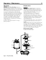
Impeller and seal replacement
1. Remove the oil fill plug and turn the pump upside
down to drain oil.
2. Remove the capscrews holding the upper motor
housing to the lower motor housing; lift off the
upper motor housing and remove the motor lead
wires from the connector to detach upper housing
from assembly. The lead wires are fitted with quick
connect terminals for this purpose.
3. Remove the capscrews holding the lower
motor housing to the volute; lift off the lower
motor housing.
4. Hold the rotor shaft assembly and unscrew the
impeller by turning it counter-clockwise. Remove
impeller and clean it.
If no more service is needed, reverse instructions
above to reassemble the pump. Reattach the motor
lead wires as shown in Figure 2, fill with clean SAE
5W-15W (ISO 22-44) mineral oil, check the oil level
and replace fill plug. Oil should cover the top of
the motor.
Shaft seal replacement
1. Follow the instructions to remove the
impeller, above.
2. Remove the stator capscrews and the spacers (if
applicable). Lift off the stator.
3. Remove the seal’s ceramic seat from the shaft
and tap the body of the seal out of the lower
motor housing.
4. Clean the seal cavity thoroughly before installing the
new seal.
NOTICE Make sure that the seal faces are clean; do
not scratch or damage the new seal face during seal
replacement. Apply gasket sealant sparingly to the
outside edge of seal body before installing the seal in
the lower motor housing.
5. Press the new seal body into position in the lower
housing cavity.
6. Press the ceramic seat onto the motor shaft. The
impeller will pull it into position.
7. Reassemble the stator and tighten the stator
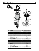
capscrews. If your pump has a capacitor (Repair
Parts Ref. 11), be sure the spacer is under it to keep
it away from the oil in the motor.
Risk of electric shock. Can shock, burn
or kill. Discharge capacitor before handling it.
Electrical shock can burn or kill.
8. Reassemble the impeller and the pump (reverse
instructions 1 through 4 in Impeller And
Seal Replacement).
9. Install new capacitor.
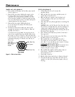
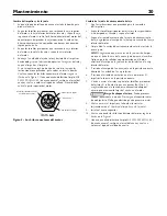
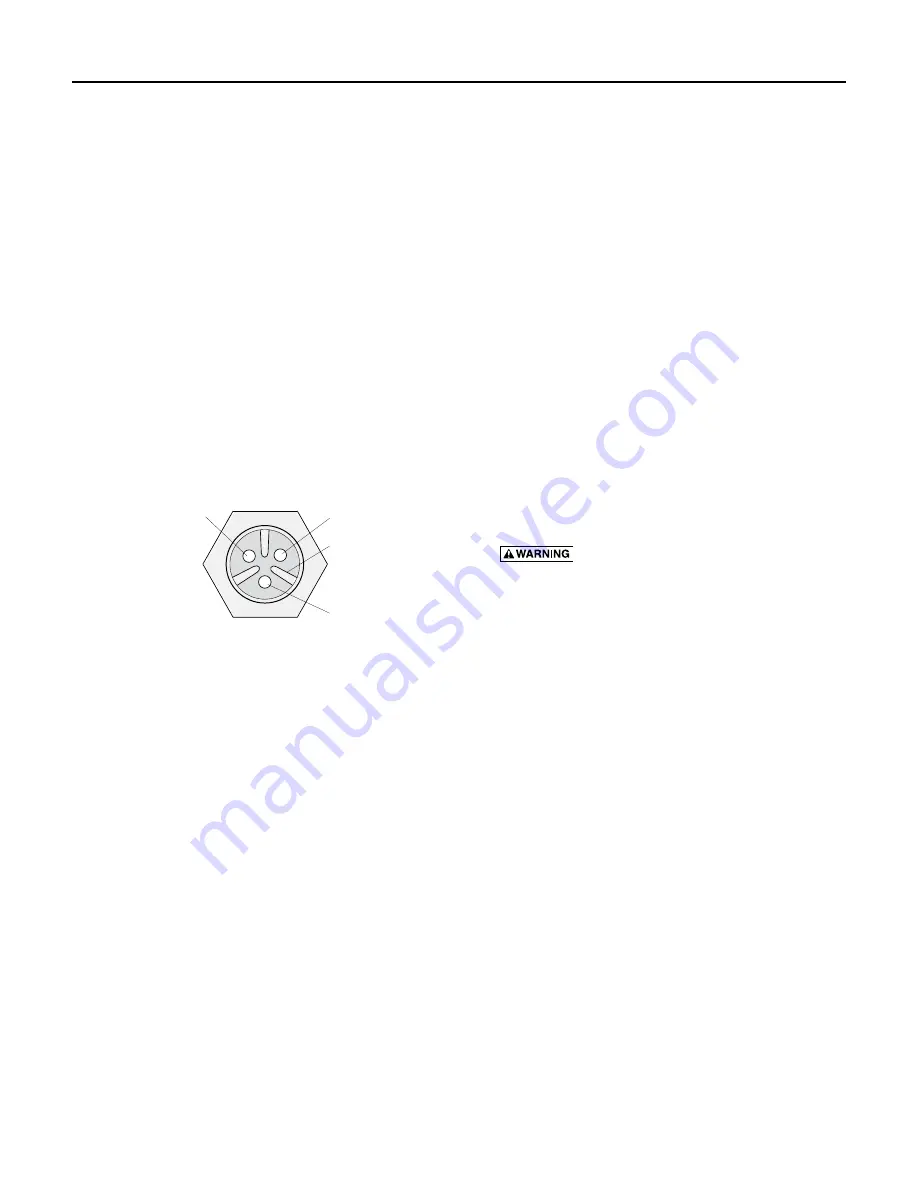
10. Reattach the motor lead wires as shown in Figure 2.
11. Fill with fill with clean SAE 5W-15W (ISO 22-44)
mineral oil, check the oil level and replace the oil
fill plug.
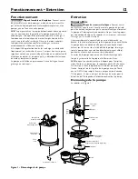
Short Divider
Either Black Wire
Either Black Wire
Green Wire
View
A-A
(connected between
the two tallest
dividers)
409 0893
Figure 2 - Motor Lead Wires
Summary of Contents for MYERS ME40MC-11-CI
Page 23: ...This page intentionally left blank ...
Page 24: ......


