background image

4

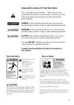
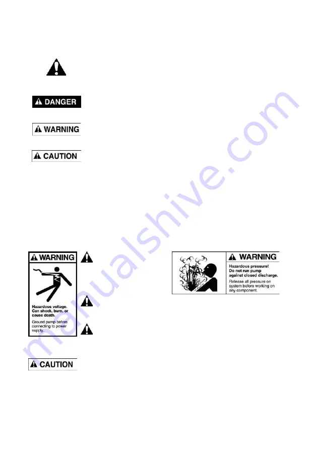
READ AND FOLLOW SAFETY INSTRUCTIONS!

This is the safety alert symbol. 

When you see this

symbol on your pump or in this manual, look for one of the
following signal words and be alert to the potential for
personal injury:

DANGER 

warns about hazards that will cause serious

personal injury, death or major property damage if ignored.

WARNING

 warns about hazards that can  cause serious

personal injury, death or major property damage if ignored.

CAUTION

 warns about hazards that will or can  cause

minor personal injury or property damage if ignored.

The label 

NOTICE

 indicates special instructions which are

important but not related to hazards.

Carefully read and follow all safety instructions in

this  manual.

Electrical Safety

Wire  motor for  correct

voltage.  See

‘Electrical’  section  of
this  manual  and
motor  label.

Ground motor before
connecting to power
supply.

Meet  National  or  local
electrical  code  for  all
wiring.

Do  not  touch  an  operating  motor.  Modern  motors
are  designed  to  operate  at  high  temperatures.  To
avoid burns when servicing pump, allow it to cool
for  at  least  20  minutes after shut-down  before
handling.

General Safety

To avoid heat build-up, over pressure hazard and
possible injury, do not use in a pressure tank
(domestic water) system. Do  not use as  a  booster
pump; pressurised suction may cause pump body to
explode.

Do not allow pump or piping system to freeze.
Freezing  can  damage  pump  and  pipe,  may  lead  to
injury from equipment failure and will void warranty.

Pump water only with this pump.

Periodically  inspect  pump  and  system  components.
Wear safety glasses at all times when working on
pumps.

Summary of Contents for ONGA 112 Series

Page 1: ...the installer or owner be unfamiliar with the correct installation or operation of this type of equipment contact the distributor or manufacturer for correct advice before proceeding with installatio...

Page 2: ...hand picked authorised Onga dealer network throughout Australia and worldwide are second to none We invest considerable time and resources training and supporting them through the Onga Training Academ...

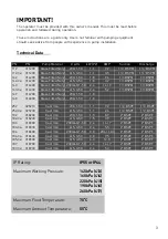
Page 3: ...PM 1 BSPM 142 3 314230 Glass Filled Noryl 415 3 50 1 8 3 2 1 BSPM 1 BSPM 143 314300 Glass Filled Noryl 230 460 1 50 2 4 14 7 1 BSPM 1 BSPM 143 3 314330 Glass Filled Noryl 415 3 50 2 4 5 2 1 BSPM 1 BSP...

Page 4: ...ual Electrical Safety Wire motor for correct voltage See Electrical section of this manual and motor label Ground motor before connecting to power supply Meet National or local electrical code for all...

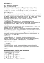
Page 5: ...intended for use by young children or infirm persons without supervision Children should be supervised at all times when near this appliance INSTALLATION Total Suction Head Feet Metres Percentage of...

Page 6: ...o other appliances on it An earth leakage or residual current protection device must be fitted to all installations rated residual operating current not exceeding 30mA A voltage surge protector should...

Page 7: ...rked and or E 230 volt single phase motors are supplied as standard with on winding thermal overload protection and are designed to plug directly into a 10 amp GPO domestic power supply to local elect...

Page 8: ...pressure and risk of explosion and scalding If pump is run continuously at no flow that is with discharge shut off or with out priming water may boil in pump and piping system Under steam pressure pi...

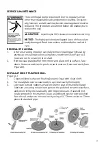
Page 9: ...shaft 2 Remove seal plate baffle from motor and place on flat surface face down Use a screwdriver to push ceramic seat out from seal cavity see Figure B INSTALLATION OF FLOATING SEAL Figure C 1 Clean...

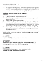
Page 10: ...TION OF ROTATING PART OF SEAL UNIT Figure D 2 Reinstall seal plate using extreme caution not to hit ceramic portion of seal on motor shaft 3 Inspect shaft to ensure that it is clean 1 Clean face of se...

Page 11: ...worn impeller Pump may be trying to push too high a column of water If so a higher head pump is required No power at outlet Use another electrical appliance that is known to work to check the power o...

Page 12: ...e power to the pump Loosen the casing bolts Check the alignment and condition of the casing o ring before retightening the bolts Replace the o ring if leaking persists Replace the mechanical seal Pump...

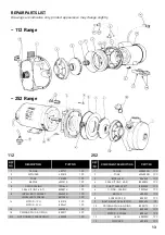
Page 13: ...800447 1PC 15 LEAD 608200K 1PC 18 PRIMING PLUG O RING 800017 2PC NS NUT DOMED 3 PHASE ONLY 603250 1PC PART NO 112 Range REF NO C 1 2 3 4 SEAL KIT INC 4 5 800583K 1PC 5 SHAFT SLEEVE KIT 6 O RING CASIN...

Page 14: ...EAL PK 25 800900 1PC 800900 1PC 800900 1PC 800900 1PC 8 IMPELLER 1PH 506353K 1PC 503843K 1PC 507103 1PC 506353K 1PC IMPELLER 3PH 801231K 1PC 503849K 1PC 1PC 1PC 9 COACH BOLT PK 10 800254 8PC 800254 8P...

Page 15: ...00207K 1PC 700207K 1PC 700207K 1PC 700207K 1PC 9 BAFFLE 401322 1PC 401323 1PC 1PC 1PC 401322 1PC 10 SEAL KIT INC SEAL ITEM 5 800890K 1PC 800890K 1PC 800890K 1PC 800871K 1PC 800890K 1PC 11 IMPELLER 1PH...

Page 16: ...ORTANT Please attach your sales invoice docket here as proof of purchase should warranty service be required Please do not return Warranty Retain for your records Purchased From Purchase Date Serial N...

Reviews: