background image

EQUIPMENT INSTALLATION 

continued

Grounding the Plumbing

It is important that the plumbing system be electrically 

grounded . When a water softener is installed a non-metalic 

bypass valve may interrupt the grounding . To maintain 

continuity, a grounding strap can be purchased at a hardware 

store . When it is installed the strap will connect the plumbing 

into the softener to the plumbing out of the softener .
If you have other water treating equipment such as; chlorinator, 

sediment filter, neutralizer, iron filter, or taste & odor filter they 

should be installed upstream of the water softener .
You may wish to consult a water professional if additional water 

treating equipment is to be installed .

Valve Layout

Outlet 1" NPT

Inlet 1" NPT

Meter 

Cable

Drain 

1/2" Tube

To Brine Tank 

3/8" NPT

Figure 5 

Drain Line Flow Control

The drain line flow control (DLFC) requires assembly 


(Figure 6) .
1 .  Locate parts and a roll of Plumber's tape .The plumbing 

adapters should be removed (Figure 8 Connector 

Assembly) .

2 . 

Wrap the tape over threads of the flow control.

3 . 

Screw the flow control and the 90° elbow together. Hand 

tighten .

4 . 

Place the ball into the flow control and insert the assembly 

into the drain line opening .

5 .  Push the assembly in and secure with the drain line clip .
90° Elbow Flow Control

Control Ball

Drain Line Clip

Figure 6 

Water Line Connection

A bypass valve system is included and will be installed on the 

water conditioning system . Bypass valves isolate the softener 

from the water system and allow unconditioned water to be 

used . Service or routine maintenance procedures may also 

require that the system is bypassed . 

IMPORTANT: The bypass valve is shipped to you in the 

bypass position (Figure 7 Bypass Operation). When the 

valve is in bypass water will not enter the softening tank. 

The water in the building will not be treated.  Figure 7 

Bypass Operation, shows the handles in the service 

position.

Once you have selected your location check the direction of 

the waterflow in the main pipe. Figure 7 Bypass Operation can 

be used to plan the new plumbing assembly .
Inspect the main water pipe . Write down the type of pipe 

(copper, plastic, galvanized etc .) . Record the size of the pipe . 

Plastic style pipes usually have the size printed on the outside . 

Other pipes can be measured for the outside diameter and 

converted into the pipe size at the store . Do not use pipe that is 

smaller than the main water pipe . 

The bypass has two fittings that connect to the plumbing. 

These connections are threaded 1" NPT .
If the main plumbing is galvanized pipe and you are installing 

copper pipe, then you must use dielectric insulating connectors 

between the two styles of pipe . 
Place the two tanks in position . The design of the tank does not 

allow for bad alignment of the connections . You may ask your 

supply store about flexable connections.

Take measurements and create a drawing of your installation . 

Include pipe lengths and elbows that are needed . If the water 

flow is from right to left you will need to cross the plumbing to 

the softener . Take the drawing to your plumbing supply store . 

Consult with their expert for installation ideas and suggestions . 

Assemble the plumbing .

WARNING:

 If pipes will be sweat soldered, do not 

connect adapters to the bypass until the 

pipes have cooled.

IN

OUT

IN

OUT

Connector 

Assembly

“H” Clip

Drain 

Line

Handles in Service

Handles in Bypass

Figure 7 Bypass Operation

WARNING:

 The inlet water must be connected to the 

inlet port of the valve. When replacing  

non-PRF Water valves, it is possible that 

the inlet and outlet plumbing is installed 

in a reversed position. Be certain the inlet 

connection on the valve is connected to the 

incoming water fitting from the water supply. 

Do not solder pipes with lead-based solder.

WARNING:

 Do not use petroleum grease on gaskets 

when connecting bypass plumbing. Use 

only 100% silicone grease products when 

installing any plastic valve. Non-silicone 

grease may cause plastic components to fail 

over time.

PRF26K, PRF34K, and PRF40K • 7

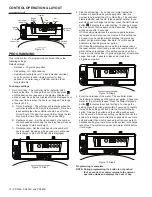
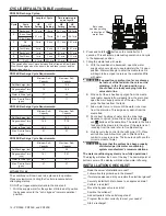
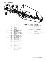
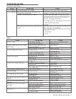
Summary of Contents for PRF26K

Page 1: ...instalaci n el mantenimiento las piezas o para obtener asistencia Comun quese con el Servicio de atenci n al cliente al 800 297 9404 Pour de tout autre renseignement concernant le fonctionnement l in...

Page 2: ...ruction Manual 10 Brine Well 1 8 Manual 9 6 7 5 4 3 2 10 EQUIPMENT INSTALLATION General Warnings And Safety Information Electrical There are no user serviceable parts in the AC adapter motor or contro...

Page 3: ...may be damaged by heat and solvents When constructing plumbing connections allow heated parts to cool and protect parts from solvents System Recharge Cycles Service Downflow Untreated water is directe...

Page 4: ...f system on the plumbing Be sure all soldered pipes are fully cooled before attaching plastic valve to the plumbing Room to access equipment for maintenance and adding salt to tank A 15 00in 381mm 36...

Page 5: ...es 2 00 AM Test your water Take a 4 5 oz sample of your water to someone who can test for hardness This information will be used to setup the control Inspection The system is shipped with several part...

Page 6: ...r Drain Figure 3 Standard Basement Before Installation Cold Water Lines Shown Soft Water Hard Water Outside Faucet Outside Faucet Bath Tub Lavatory Toilet Kitchen Laundry Tubs Pump or Meter Hot Water...

Page 7: ...ition Once you have selected your location check the direction of the waterflow in the main pipe Figure 7 Bypass Operation can be used to plan the new plumbing assembly Inspect the main water pipe Wri...

Page 8: ...increase by 2 feet 61 cm for each additional 10 psi 69 bar of water pressure at the drain connector 4 Where the drain line is elevated but empties into a drain below the level of the control valve fo...

Page 9: ...etting Hardness Button Press to display the hardness setting for 5 seconds Press again during the 5 seconds to change the setting by 1 grain per gallon Press and hold to change rapidly Flow Indicator...

Page 10: ...with the HC high capacity setting If you want to check or change the setting press the Salt Amount button to display the current setting To change it press the Salt Amount button again within 5 second...

Page 11: ...hrough each position Quick Cycle to Service Position Simultaneously press and and hold for 3 seconds during any regeneration cycle The control will skip the remaining regeneration cycles and return to...

Page 12: ...ith water A With the conditioner in backwash open the water supply valve very slowly to approximately the 1 4 open position Water will begin to enter the media tank Air will begin to be purged to drai...

Page 13: ...y 1 Dosage A Polystyrene resin 1 2 fluid ounce 35 5 ml per cubic foot B Non resinous exchangers 0 8 fluid ounce 23 7 ml per cubic foot 2 Salt tank softeners A Backwash the softener and add the require...

Page 14: ...927 Resin Tank Assy 8 x 44 PRF26K 4001884 Resin Tank Assy 9 x 48 PRF34K 4001882 Resin Tank Assy 10 x 44 PRF40K A Resin Tank B Lower Distributor Assembly C Upper Basket D Conditioning Resin TANK ASSEMB...

Page 15: ...K E 3021829 Assy Refill Control 0 33 gpm F 4001889 Kit O ring 360 Valve G 3027839 Meter Assembly 2 1 1000811 120 VAC 60 Hz N America Plug 3 1 3031825 Kit O ring Manifold 4 1 4000886 Bypass Valve Assem...

Page 16: ...t D Brine Tube 3 8 x 60 E Cap Brine Well 4 Dia Caplug STP 4 F Brine Float w One Grommet As purchased G Air Check Assembly H Tubing Insert Brass 2 1 CH34393 1 Cover and Brine Tank 14 x 34 3 1 CH20774 B...

Page 17: ...valve discs Hard water leakage after recharge Improper recharge Repeat recharge after making certain correct salt dosage was set Leaking of external bypass valve Replace bypass valve O Ring around ris...

Page 18: ...Flapper Positions When the control cover is removed the flappers and camshaft are visable Figure 18 Injector Cap Refill Control Cap Figure 18 TROUBLESHOOTING continued 18 PRF26K PRF34K and PRF40K...

Page 19: ...that 3350 grains of total hardness exchanged per pound of salt based on NaCl equivalency 477 grams of total hardness exchanged per kilogram of salt and shall not deliver more salt than its listed rat...

Reviews: