background image

P/N  520209

4

Rev. A  7-25-03

SECTION V.

INSTALLATION

Receiver

The functional range of the wireless remote (from Hand-held Remote to Receiver)
is approximately 150 ft. line-of-sight.

The receiver should be mounted at a convenient location (on a flat vertical surface)
a minimum of 5 ft. above ground level to optimize the functional range of the
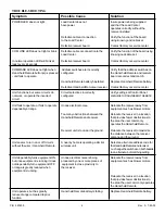
hand-held unit.  See Figure 1 for major features.

CAUTION

The receiver should be mounted a minimum of 8 to 10 feet away from any air blower,
which may be part of the equipment set.  The receiver will not operate properly if it is
close to a blower that is operating.

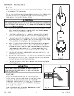
1. In order to mount the receiver, it will be necessary to remove the two retaining

screws located on the underside of the transceiver, and carefully slide the
transceiver case up and off of its back plate.

2. Temporarily position the back plate against its mounting surface so that the

receiver is oriented in an upright position (with antenna pointing upwards).

3. The circuit board will need to be temporarily removed.  Slide the board up and

out of the back plate.  Use a pencil to mark the four mounting points, and drill
3/16 in. dia. holes.  Insert the four plastic anchors (provided).

4. Feed a UL approved four 22AWG conductor cable through one of the drain

holes at the bottom of the receiver enclosure.  The preferred wire color
scheme is: red, yellow, green, and black.  If the drain holes are not used, drill
a hole through the bottom of the back plate and seal using a fitting with a
few feet of conduit or some other sealant between the case and the cable.

5. Reposition the back plate over the mounting points and secure with the four

mounting screws (provided).

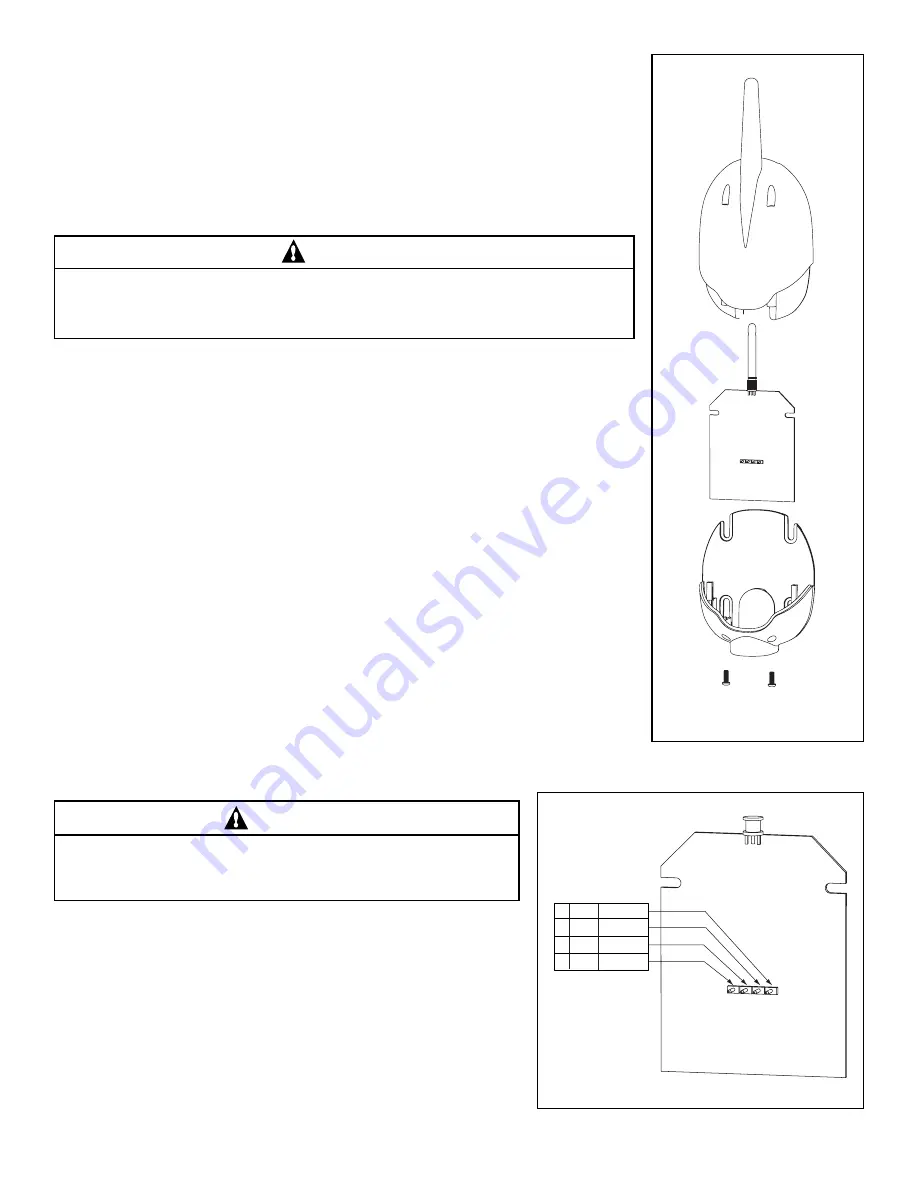
6. Strip the leads of the wires about ¼ in. and attach to controller screw terminals

of terminal plug as shown in Figure 2.  Carefully slide the circuit board back
into the back plate and connect the terminal plug.

7. Then slide the Receiver case back onto the back plate, and secure using the

two retaining screws.

CAUTION

Water damage may occur if the enclosure retaining screws are
not secured or a new hole is drilled for the cable and not sealed.
Do not seal drain holes.
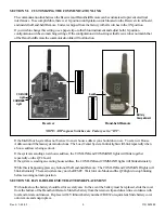
Load Center

Feed the four conductor cable from the receiver up the low
voltage raceway.  Open the control panel and fold down to make
connections.  To the left of the board are the COM PORT
connector(s).  Strip the leads of the wires about ¼ in. and attach
to controller screw terminals of any COM PORT terminal plug
following the wiring diagram.

Close control panel, high voltage cover panel, and Load Center
door.  Turn power to system back on.

4

15V

RED

3

+D

YELLOW

2

-D

GREEN

1 GND

BLACK

Figure 2.

Figure 1.

Summary of Contents for QuickTouch QT4

Page 1: ...amage Call 800 831 7133 for additional free copies of these instructions WARNING IMPORTANT SAFETY INSTRUCTIONS READ AND FOLLOW ALL INSTRUCTIONS SAVE THESE INSTRUCTIONS Pentair Pool Products 1620HawkinsAve Sanford NC27330 919 774 4151 10951WestLosAngelesAve Moorpark CA93021 805 523 2400 WARNING Risk of electrical shock or electrocution It is required that the main power into the home be switched of...

Page 2: ...emote is capable of duplicating any four circuits it has been preset at the factory to control the following Spa Push button activates the Spa circuit A Push buttonactivatesAuxiliary1circuit B Push buttonactivatesAuxiliary2circuit C Push buttonactivatesAuxiliary3circuit If you would like to control circuits other than Spa Aux1 Aux2 and Aux3 it is possible to make adjustments through the Indoor Con...

Page 3: ...on on your wireless remote press the top button at right The arrow indicates which button your are working on Hint The first button of the wireless remote is labeled SPA so configure this button for the spa mode as shown in the photo 3 To configure the other three buttons on your wireless remote repeat the process using the next three buttons at right 2 Use the DOWN UP buttons to scroll through th...

Page 4: ...WG conductor cable through one of the drain holes at the bottom of the receiver enclosure The preferred wire color scheme is red yellow green and black If the drain holes are not used drill a hole through the bottom of the back plate and seal using a fitting with a few feet of conduit or some other sealant between the case and the cable 5 Reposition the back plate over the mounting points and secu...

Page 5: ...a house address is being sent out If the system is sending a new house address the COM LINK and COMMAND lights will blink together repeatedly on the QT4 board If the system is sending an existing house address the COM LINK and COMMAND lights will blink alternately While this is happening press any button of the Hand held Remote The COM LINK and COMMAND lights will blink alternately The main system...

Page 6: ...figured MENU SETUP ADV REM QT REMOTE circuit Unit fails to operate or fails to operate Undue electrical noise Relocate the receiver away from dependably at range equipment such as blower motors Too many obstructions between the Relocate the receiver in a location Hand held Remote and receiver that provides fewer obstructions to the area the user commonly operates the Hand held Remote Receiver unit...

Page 7: ... P N 520209 For questions repairs replacement parts or information on possible Authorized Service Centers within your vicinity call Pentair Pool Products 800 831 7133 Or visit us on the Internet at www pentairpool com ...

Page 8: ...P N 520209 8 Rev A 7 25 03 Pentair Pool Products 1620HawkinsAve Sanford NC27330 919 774 4151 10951WestLosAngelesAve Moorpark CA93021 805 523 2400 ...

Reviews: