Installing New Seal
1. NOTICE: Seal faces are highly polished and lapped.
Handle with care. Any mar, nick or scratch on seal
face will cause it to leak. BE SURE to install with
polished faces toward each other.
2. Clean polished surface of ceramic seat with
clean cloth.
3. Wet O-Ring around ceramic seat with liquid soap.
4. Press stationary (ceramic) half of seal into cavity
firmly and squarely with thumb pressure. If it does
not seal properly, remove and place face up on
bench. Re-clean adapter/seal plate cavity. Seal
should now seat correctly.
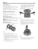
5. If seal does not seat after recleaning adapter/seal
plate cavity, place a cardboard washer over polished
face of seal and carefully press into place using a
piece of 1” standard pipe as a press. (Figure 6).
NOTICE: BE SURE you do not scratch seal face.
6. Dispose of cardboard washer and recheck seal face
to be sure it is free of dirt, foreign particles, scratches
and grease.
7. Inspect shaft and shaft sleeve to be sure they
are clean.
8. Re-install O-Ring, shaft sleeve and slinger (Ref. No.
4) on shaft.
NOTICE: A small amount of grease or Never-Seez
under shaft sleeve will help prevent shaft and sleeve
from freezing together when pump is in service.
9. Remount adapter/seal plate to motor, being careful
not to scratch seal face.
10. Apply liquid soap to inside diameter and outside
face of rubber drive ring on rotating half of seal.
11. Slide seal assembly onto shaft sleeve (sealing face
first) far enough so that seal spring is located on shaft
sleeve. NOTICE: Be careful not to nick carbon seal
face when passing it over end of shaft sleeve.
12. Slide impeller and gaskets (Ref. Nos. 12 and 11) onto
shaft with key (Ref. No. 3) in position. Be sure to
maintain proper order as shown in Repair Parts.
13. Install washer, gaskets, and impeller screw (Ref. Nos.
14, 15, 16, 17) on end of shaft and tighten screw
until it is snug. This should locate seal in place and
bring seal faces together.
14. Re-install motor, adapter and impeller assembly on
volute, using new gasket (Ref. No. 7).
15. Re-install motor hold- down bolts.
16. Check all bolts for tightness.
17. Pumps below water level: Close drains; open
isolation valves to fill pump. Pumps above water
level: Prime pump. Open isolation valves if they
were closed at disassembly.
18. When pump is full, close air vents.
19. Reconnect power to pump and system is ready
for operation.
1" Standard Pipe
Stationary Seat
Cardboard
Washer
(Supplied with seal)
1422 1294
Figure 6
Service 8
Summary of Contents for S40093
Page 11: ...This page intentionally left blank...
Page 12: ......


