background image

2875 0697ASB

“SSJ” Series

Installation/Operation/Parts

For further operating, installation,  

or maintenance assistance: 

Call 1-888-782-7483

OWNER’S MANUAL

Vertical Jet Pumps

© 2013 Pentair Ltd. All Rights Reserved. 

S724 (REV 01/14/13)

293 WRIGHT STREET, DELAVAN, WI 53115  WWW.STA-RITE.COM
PH: 888-782-7483

Summary of Contents for SSJ Series

Page 1: ...on Parts For further operating installation or maintenance assistance Call 1 888 782 7483 OWNER S MANUAL Vertical Jet Pumps 2013 Pentair Ltd All Rights Reserved S724 REV 01 14 13 293 WRIGHT STREET DELAVAN WI 53115 WWW sta rite COM PH 888 782 7483 ...

Page 2: ...together Do not touch metal screwdriver blade or capacitor terminals If in doubt consult a qualified electrician General Safety Do not touch an operating motor Modern motors can operate at high temperatures To avoid burns when servicing pump allow it to cool for 20 minutes after shut down before handling Do not allow pump or any system component to freeze To do so will void warranty Pump only wate...

Page 3: ...phase motors must be protected by three leg ambient compensated extra quick trip overload relays of the recommended size or the warranty is void Your only remedy and STA RITE s only duty is that STA RITE repair or replace defective products at STA RITE s choice You must pay all labor and shipping charges associated with this warranty and must request warranty service through the installing dealer ...

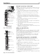
Page 4: ...asy to handle and does not usually require a block and tackle for installation and removal PLASTIC PIPE INSTALLATION DOUBLE PIPE NOTE Use PTFE pipe thread sealant tape tape on all male threads on plastic pipe and fittings to prevent air leaks in suction piping 1 Inspect ejector to make sure that nozzle and venturi openings are clean and clear 2 Inspect pipe for any foreign matter or obstructions I...

Page 5: ...INGLE PIPE EJECTOR INSTALLATION Single pipe installations require see Figure 3 a Galvanized steel pipe b Leather packer type ejector with built in foot valve c Turned couplings supplied with packer type ejector d Well casing adapter 1 Connect ejector to first length of pipe Use pipe joint compound sparingly on male threads Consult Table II for proper venturi and nozzle 2 Lower pipe into casing Use...

Page 6: ...t is needed See Figure 4 for typical standard tank installation To connect AVC to pump thread a 1 8 compression fitting into tapped hole on the front of the pump Cut tubing to length to reach AVC assemble to fitting on pump and to AVC on tank See installation instructions provided with tank and AVC PRECHARGED TANK CONNECTION When a precharged tank is used no AVC is necessary See Figure 5 for typic...

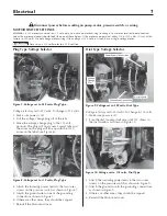
Page 7: ...ach the incoming power leads to the two outer screws on the pressure switch as shown in Figure 9 4 Attach the ground wire to the grounding connections as shown in Figure 9 5 If there are other wires they should be capped 6 Reinstall the Motor end cover Disconnect power before working on pump motor pressure switch or wiring NOTICE 1 2 HP motors are wired for 115 volts only and have no motor wiring ...

Page 8: ...id copper wire at least as large as the power supply wires 2 There must be a solid metal connection between the pressure switch and the motor for motor grounding protection If the pressure switch is not connected to the motor connect the green ground screw in the switch to the green ground screw under the motor end cover Use a solid copper wire at least as large as the power supply wires 3 Connect...

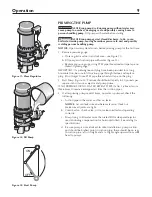
Page 9: ...ant tape on the plug 2 Start Pump Figure 13 Pressure should build rapidly to 50 pounds per square inch or more as ejector and pump prime IF NO PRESSURE OR NO WATER REPEAT STEPS IN No 1 above two or three times to remove entrapped air from the suction pipes 3 If after priming pump several times no water is pumped check the following a Suction pipe in the water and has no leaks NOTICE Air can leak i...

Page 10: ...aced replace the shaft seal Keep one on hand for future use Be sure to prime pump before starting IMPORTANT Check motor label for lubrication instructions The mechanical shaft seal in the pump is water lubricated and self adjusting IMPORTANT Drain pump when disconnecting from service or when it might freeze WINTERIZING Figure 18 1 Precharge Tank a Remove drain plug on pump body and disconnect pres...

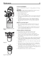
Page 11: ...h clean cloth 2 Wet the O Ring in the ceramic seat with soap solution 3 Press seat into cavity firmly and squarely with finger pressure Figure 21 If seat will not locate properly place cardboard washer over polished face of seat and use piece of 3 4 standard pipe for pressing purposes 4 Dispose of cardboard washer and again make sure that polished surface of seat is free of dirt or foreign particl...

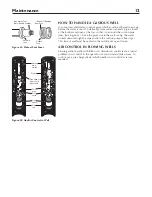
Page 12: ... gas This type of well must be vented to the outside of any enclosure AIR CONTROL IN FLOWING WELLS Flowing wells or wells with little or no drawdown could create a special problem in air control in the operation of your standard tank system In such cases a pre charged tank which needs no air control is recom mended Pipe strap or wire to hold pipe sleeve Pipe sleeve Pipe cap Tail pipe Foot valve Ej...

Page 13: ...12 19e QTY 1 Adjusting Screw 1 4x20x3 4 U30 537ZP 1 2 Spring Follower J24 7 1 3 Diaphragm J20 5 1 4 Valve Guide J42 4 1 5 Diaphragm and Valve Guide Assembly J120 14 1 6 Valve Seat Only J66 15 1 7 Regulator Body with Valve Seat J112 8E 1 8 1 2x1 8 NPT Reducer Bushing 1 9 Pressure Gauge U239 3 1 10 Adjusting Screw J28D 1 11 10 32x1 2 Machine Screws 6 12 Regular Bonnet J52 5ZZ 1 13 Spring Button J48 ...

Page 14: ...212 19E 1 7A Pressure Gauge U239 3 U239 3 U239 3 1 8 5 16 18x5 8 Capscrews U30 58ZP U30 58ZP U30 58ZP 6 9 1 NPTx2 Nipple U37 55GPT U37 55GPT U37 55GPT 1 10 Tube U37 672P U37 672P U37 672P 1 11 1 4 NPT Barbed Fitting U111 211T U111 211T U111 211T 1 12 Pressure Switch U217 1215 U217 1215 U217 1215 1 13 1 2 Locknut U36 112ZP U36 112ZP U36 112ZP 1 14 Connector J43 13C J43 13C J43 13C 1 15 Impeller J10...

Page 15: ...p house Foot valve and or strainer are Raise foot valve and or strainer above bottom of water source buried in sand or mud Clean foot valve and strainer Water level is too low for shallow well A deep well jet package may be needed over 25 ft to water setup to deliver water to deliver water Pump does not Water level in well is lower than A new jet and venturi combination may be needed deliver water...

Page 16: ......

Reviews: