


EN-TraceTekTT1100OHP-IM-H58263 01/15
THERMAL BUILDING &
INDUSTRIAL HEAT TRACING SOLUTIONS
3 / 8
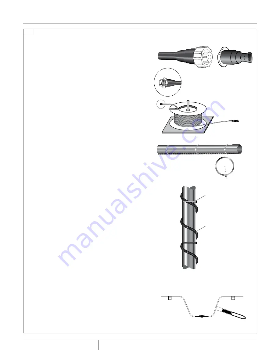
Maximum
offset = 1/4 in
End termination
Cable connector with pins
toward alarm module
Tie-wrap
Sensor
cable
TraceTek
Systems
Service
loop
4
connect, orient, install, and test each length of sensing cable in
sequence
1.
connect
a Modular End Termination (TT-MET-PC) to the first sensing-cable
length to be installed.
2.
orient
sensing cable so the connector used with the end termination will
be the furthest away from connection to the TraceTek alarm module. Work
out from the alarm module connection. For sensing cable on reels (lengths
over 10 feet (3 m)), put the reel on an axle and pull the cable out.
3.
install
sensing cable in accordance with the leak detection layout plan.
A. For pipeline applications:
• Position the cable along the bottom of the pipe and use tie wraps to
secure the cable at the 6 o’clock position. Maintain cable position
within 1/4 inch (6 mm) of 6 o'clock position.
• Tie wraps should be long enough to go around the pipe and the sen-
sor cable.
• Use one tie wrap every 12 in to 18 in (300 to 450 mm) along the pipe
with extra tie wraps at fittings or bends as needed.
important
: It is the installer’s responsibility to position the sensor cable
correctly. The cable must trace the lowest point of the pipe or fittings
such that any water leaking from the pipe or fittings will drip onto the
cable surface as it drips off the bottom of the pipe or fitting. Do not
install the cable on the top or side surface of a pipe. Do not spiral the
cable on horizontal pipe.
exception
: If the cable is used to trace vertical pipe, the cable should be
spiraled around the pipe and secured with tie-wraps.
B. For sumps, containment trenches, and subfloor applications:
• Pull the cable alongside the installed hold-down clips; minimum bend
radius is 2 in (50 mm). Leave 6 in (150 mm) of sensing cable on each end
for the connector service loop.
important
: Verify that the adhesive securing the hold-down clips has
dried; liquid adhesive must not contact the cable.
Push sensing cable into the hold-down clips and position the sensing
cable to lay flat on the surface to be monitored. Secure by snapping
hold-down clip end into base.
4.
test
each length of sensing cable after installing it and before attaching
it to cable already installed. Confirm that the sensing cable is clean and
intact by following the Sensing Cable Test Procedure.
5.
connect
the sensing cable to the cable string (lengths of sensing cable
connected in series) previously installed.
For sumps, containment trenches, and subfloor applications:
• Leave a service loop at each connector as shown.
• Mark the connector position on the layout plan.
• Install TraceTek mapping tag (TT-TAG).
•
note
: As an extra precaution on large installations, periodically test the
entire cable string to confirm that all installed sensing cable is still clean
and intact.
• Unplug the end termination and connect it to the next length of sensing
cable to be installed.
6.
repeat
the installation sequence for each length of cable.


